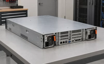
CRPS2700TS5 is a 2700 W class Titanium CRPS power module with a nominal +54 V main output and a separate +12 VSB / 2 A standby output. Its useful distinction is the sharp difference between low-line and high-line capacity: a published selection sheet lists 24.0 A at 100–127 Vac and 50.0 A at 200–240 Vac. At nominal 54 V, those currents represent about 1.30 kW and 2.70 kW respectively. A server that needs the full rated class therefore needs a suitable high-line supply; the broad input-voltage range alone does not promise 2700 W at every outlet. This article explains how to turn those published figures into a reliable rack power plan.
The two output tiers define the deployment
The manufacturer’s public CRPS listing identifies CRPS2700TS5 as a 2700 W, +54 V unit and lists +54 V / 24.1 A and +54 V / 50 A. A separate CRPS2700TS5/3200TS5 selection sheet associates 24.0 A with 100–127 Vac input and 50.0 A with 200–240 Vac or 240 Vdc input. The 0.1 A difference at low line is a difference between public documents, not a useful basis for adding load. Obtain the supplier’s revision-controlled rating table before setting an operating limit.
The two figures describe alternative conditions for one output, not two outputs to be added. Nor should the 90–264 Vac input range on the manufacturer’s listing be read as a flat-power range. Its 2700 W designation describes the high-line class. If a site runs a rack at 120 Vac, sizing the server from 2700 W would overstate the published low-line capacity by roughly a factor of two. Even at a nominal 208 Vac feed, the equipment’s allowed input at its socket should be checked against the exact rating table and its tolerances.
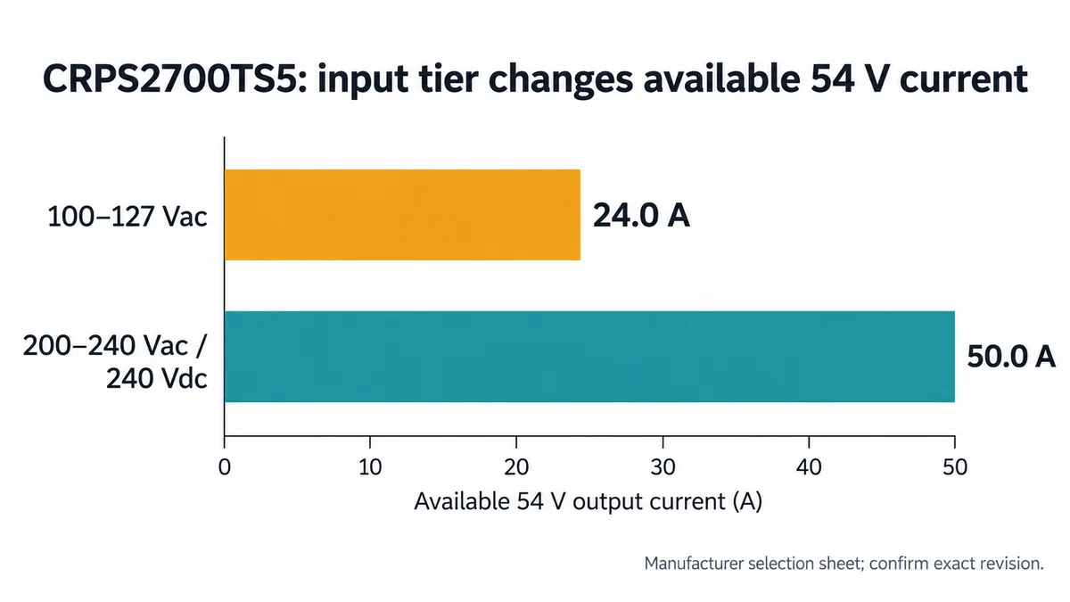
Consider a hypothetical server with 1.8 kW of measured sustained demand on its intermediate bus. That demand is below the module’s nominal 2.7 kW high-line class, yet above the approximately 1.30 kW represented by its published low-line current. Changing the facility feed can therefore change whether the same hardware configuration remains within the module’s documented operating tier. This is not an estimate of any particular server’s consumption; it illustrates why a nameplate should be paired with the actual receptacle voltage.
Translate the 54 V current into a load budget
At 54 V nominal, 50 A multiplied by 54 V equals 2700 W. This simple multiplication explains the high-line rating, but it does not define the complete guaranteed output envelope. Voltage tolerance, standby demand, temperature derating, and supplier rules for combined outputs can affect an installation. The public page lists the +12 VSB / 2 A rail separately; its 24 W arithmetic ceiling should not be casually added to the 2700 W headline without the manufacturer’s combined-power rule.
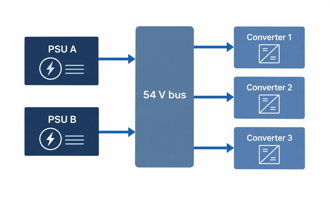
Start a practical budget at the point where the 54 V module feeds the system distribution board. Add the power drawn by each downstream converter at its input, not just the power delivered to CPUs, GPUs, memory, drives, and fans. A local converter delivering 800 W to its load draws more than 800 W from the 54 V bus because conversion has losses. Use the converter’s measured or specified efficiency at the actual load and temperature, rather than assuming one efficiency number for every branch. Distribution copper and connector losses also consume a small but sometimes important portion of the upstream allowance.
For example, if three converters each require 600 W at their 54 V input and auxiliary bus loads require another 100 W, the bus demand is 1900 W before any further margin. At 54 V nominal that is about 35.2 A. The example fits within a 50 A high-line current point but exceeds a 24 A low-line point. It says nothing about a real CRPS2700TS5 system’s transient behavior, output-voltage tolerance, or reserve for a failed module. Those must be handled separately. Its value is to reveal the branch currents that need to be compared with the correct input tier.
A 54 V intermediate bus also changes where conversion heat is located. CRPS2700TS5 converts the facility input to the intermediate rail, while board-level converters produce the low-voltage rails required by components. Moving large amounts of power through the chassis at 54 V generally uses less current than moving the same power at 12 V, but the local converters need board area, cooling, protection, and a controlled startup sequence. The intended system should be designed for this distribution arrangement. A 12 V backplane does not become compatible because it accepts a mechanically similar CRPS shell.
Why 2700 W can be a useful limit in a 54 V platform
The same manufacturer lists CRPS3200TS5 as a higher-power 54 V model in the 185 × 73.5 × 40 mm family. Its published high-line current figures extend above the 50 A point of CRPS2700TS5. That does not make the larger module an automatic upgrade. In a server whose verified peak bus demand stays below 50 A under the applicable input condition, a 2700 W class module may fit the load envelope without selecting capacity the application cannot use. The choice also depends on redundancy objectives, sourcing, thermal characteristics, and the exact approved chassis interface.
Mechanical sameness is a screening convenience, not a replacement approval. The public CRPS2700TS5 listing gives 185 × 73.5 × 40 mm, FR airflow, and a 0–55 °C operating range. An apparently matching CRPS3200TS5 has the same public envelope, but the complete connector pin assignment, output enable behavior, telemetry expectations, current-share implementation, and chassis qualification are not established by those dimensions. A platform vendor may approve one revision and not another. The extra power rating may also imply a different permitted input or cooling condition.
The Powernexu CRPS2700TS5 product page is useful for its public model identity, rail, input range, size, and efficiency class. For a purchase or substitution, request the actual part and revision data from the supplier or platform maker. The page is a starting point for matching a 54 V product family, not an interface-control document.
Account for the surviving module, not the pair
Two modules in a redundant chassis may share load during normal operation. If the requirement is continued operation after one module is removed or fails, the remaining module must carry the entire relevant demand at its own input condition. A pair of CRPS2700TS5 units on 200–240 Vac does not provide 5400 W of 1+1 protected output. For a simple two-module arrangement, the protected load must fit inside one module’s supported output envelope, subject to system-level fault and sharing behavior.
With the hypothetical 1900 W bus load above, one high-line 50 A module could satisfy the steady arithmetic while one low-line 24 A module could not. The example deliberately avoids claiming that this system survives a module fault: transfer dynamics, output capacitance, current sharing, converter ride-through, wiring, and protection coordination determine whether it actually does. A fault can also remove an AC branch or distribution component rather than just one power module. Define the failure being protected against before assigning a redundancy label.
Mixed feeds deserve particular attention. If one PSU receives high line and the other receives low line, the two nominally identical modules may have different allowed capacities. After loss of the high-line side, the low-line survivor may be limited to the lower published current. The system may need a load-shedding policy, a smaller operating load, or two appropriately provisioned high-line feeds to meet its continuity objective. The situation is easy to miss when an equipment inventory records only “two 2700 W PSUs.”
A 54 V distribution board and its connectors also need to tolerate the surviving current path. If both modules normally share 40 A total, a single remaining path could be asked to carry all 40 A after a failure. Contact ratings and thermal behavior must be checked for that state, not just the 20 A share observed during healthy operation. The exact current-share and fault-isolation capabilities require platform documentation; the public selection sheet’s mention of active current sharing does not settle the system implementation.
Use the published envelope without overreading it
The manufacturer lists a broad 90–264 Vac or 180–320 Vdc input range. The selection sheet supplies explicit 100–127 Vac, 200–240 Vac, and 240 Vdc output points. These documents do not, on their own, tell a reader the maximum output at every voltage between the listed points. In particular, interpolating an invented current limit for a brownout or for 180 Vdc would be unsound. If the site operates near a boundary, obtain the complete input-derating curve and define the lowest expected voltage at the PSU connector, including distribution drop.
Thermal conditions matter for the same reason. The public 0–55 °C range says where the product may operate, but it does not prove that the full 50 A is available at every inlet temperature, altitude, airflow restriction, or fan condition. An FR airflow designation should be translated into an actual intake-to-exhaust direction for the chassis. A dense rack can raise the inlet temperature even if the data hall’s average reading looks comfortable. A revision-controlled thermal specification should resolve any output derating and the required air path.
“Titanium” identifies a claimed efficiency class; it is not a universal percentage to insert into a rack energy estimate. Input voltage and load fraction affect conversion efficiency, and the 54 V-to-load converters add further losses. The manufacturer’s public listing also enumerates safety and market marks. Those marks should be checked against the exact purchased part, region, and current certificate scope when compliance matters. A public product-family list is not a substitute for the certification record attached to a shipment or chassis configuration.
The selection sheet mentions hot-pluggable operation, cold redundancy, and PMBus compliance. These are useful leads for integration but do not disclose the exact connector sequence, management commands, addresses, event semantics, or live-replacement procedure. A server controller must use the applicable technical manual and platform firmware profile. A technician should use the system maker’s service procedure, especially when the surviving unit may already be near its permitted tier.
The boundary between a model match and an approved replacement
A spare labeled CRPS2700TS5 is a candidate only after its electrical and mechanical revision matches the host’s approved configuration. Confirm the label and orderable part number, the input tier required by the rack, the 54 V main and 12 VSB standby rails, airflow orientation, retention features, and the actual mating interface. If the host uses management telemetry or current sharing, compare those functions in the revision-specific documents. A superficially similar 12 V CRPS module can be especially hazardous because its enclosure may suggest interchangeability while its rail does not.
For a new platform, state the required bus current at steady and peak load, the lowest facility voltage the server must tolerate, and the intended failure mode. Those three quantities will expose whether CRPS2700TS5’s published 24 A low-line and 50 A high-line points can serve the design. Then resolve the information that public listings do not provide: detailed derating, combined-output limits, connector definition, fault response, and transient performance. This sequence keeps the published figures useful while leaving approval to the documents that actually control integration.
The practical result is narrow and clear. CRPS2700TS5 is a 54 V, 2700 W class option for a platform that can use its high-line 50 A output tier. At low line, the published approximately 24 A tier changes the viable load and redundancy plan. The product name is therefore less informative than the voltage available at the PSU inlet and the current the surviving 54 V path must deliver.