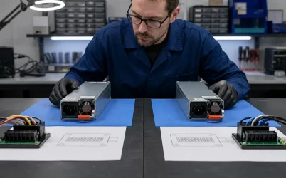
A quad output open frame power supply should be chosen by mapping four loads to four documented outputs across startup, normal operation, transitions, shutdown, and faults. “Quad output” means four nominal output rails; it does not necessarily mean four isolated, independently regulated, or independently protected supplies. Compare candidates using a four-rail load-and-sequence matrix, then test every operating state against the exact model’s individual rail ratings, grouped limits, total output limit, regulation conditions, and cooling requirements. If the documentation cannot explain the worst simultaneous state, the model is not yet a defensible match.
Four named outputs are not four independent power supplies
A product listing may identify four voltages without describing how those outputs interact. Depending on the converter design, one rail may be the main regulated output while auxiliary rails depend partly on transformer coupling and loading elsewhere. Another design may regulate several outputs more tightly or create one output through a downstream regulator. Return connections, protection behavior, and adjustment provisions also vary by model.
For that reason, begin with the behavior required by the four loads rather than a preferred voltage combination. A control system might need separate power for digital logic, analog circuitry, communications, and actuators. Another machine might use positive and negative analog rails alongside a logic rail and a higher-voltage peripheral rail. The labels alone do not reveal whether those loads can coexist within the supply’s documented operating envelope.
The same principle applies to a dual output open frame power supply, but a four-output design creates more simultaneous combinations. A light load on one auxiliary rail, a pulsed demand on another, and a startup surge on a third can occur while the fourth rail is already supporting sensitive electronics. Evaluating four isolated maximum-current figures would miss those interactions.
Give each rail a load role and a time-dependent requirement
The useful matrix has one row for each rail and enough columns to describe how its load behaves. It should not begin as a copy of a catalog table. First record what the machine needs at the load terminals; model-specific limits can then be placed beside those requirements during comparison.
| Matrix field | Rail V1 | Rail V2 | Rail V3 | Rail V4 |
|---|---|---|---|---|
| Load function | Primary logic or controller | Analog or sensor circuitry | Communications or peripheral load | Actuator, drive, or auxiliary load |
| Required voltage behavior | Nominal value and tolerance at the load | Noise-sensitive range and polarity | Normal and idle range | Normal range and permitted droop |
| Current profile | Standby, boot, and normal demand | Quiescent and active demand | Idle and transmission demand | Inrush, pulse, and sustained demand |
| Sequence relationship | First, simultaneous, or unrestricted | Before or after V1 | Enabled by another rail or independent | Delayed until control is valid |
| Shutdown requirement | Minimum retention or decay behavior | Maximum permitted reverse sequence | Data-preservation or reset need | Immediate removal or controlled decay |
| Fault consequence | Loss of control | Measurement corruption | Loss of communication | Unexpected motion or process interruption |
The functions in this example are illustrative; actual rail assignments should reflect the machine. If V2 is a negative rail, document its polarity relative to its return instead of treating the minus sign as a negative contribution to total power. A conventional source output may not be able to absorb energy returned by a load. Regenerative or backfeeding behavior therefore needs an explicit path in the host design or documented support from the supply.
After defining the rail rows, add columns for system states. Useful states often include input application, standby, controller boot, peripheral enable, actuator engagement, maximum normal activity, controlled shutdown, emergency shutdown, and recovery after a fault. The worst state may be a short transition rather than the condition with the highest sustained power.
Read exact-model documentation in four layers
Quad-output families often contain several voltage combinations. A family name or distributor title is therefore only a discovery aid. The selected part number must be traced to its own output table, notes, mechanical drawing, and environmental conditions.
Individual output limits
For each rail, identify the permitted current range, voltage tolerance, ripple or noise condition, and any peak-load provision. A stated maximum current is not automatically available at every temperature, input voltage, orientation, or airflow condition. Minimum-load notes also matter where an auxiliary output depends on loading elsewhere for regulation.
Grouped constraints
Some models specify a limit shared by two or more rails. Such a constraint cannot be checked by reading each output independently. The applicable currents or powers must be combined exactly as the manufacturer defines them, using the simultaneous state from the load matrix.
Total output power
For an initial state calculation, add the power delivered by all four source rails: Pstate = |V1|I1 + |V2|I2 + |V3|I3 + |V4|I4. Absolute voltage magnitude is used for a negative source rail because it still contributes positive delivered power. This arithmetic checks total output demand, but it does not override individual-current, grouped-power, transient, or thermal restrictions.
Conditions and footnotes
Footnotes can determine whether the attractive headline configuration applies to the intended machine. The MEAN WELL RQ-125 series datasheet, for example, presents output information by exact variant and includes conditions and notes that must remain attached to those ratings. This is the appropriate level of evidence for comparison: manufacturer documentation for the exact model, not a distributor title that merely lists four voltages and a family wattage.
Startup and shutdown can disqualify an otherwise adequate power map
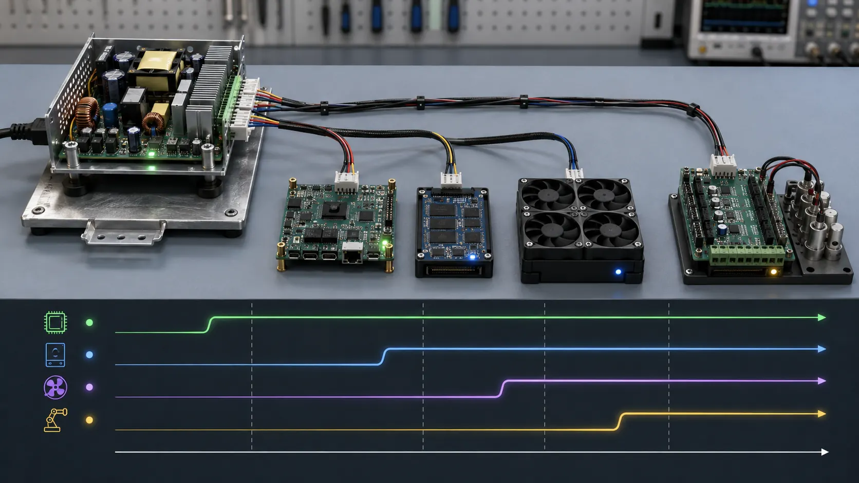
A steady-state matrix will not reveal whether the machine starts correctly. Four loads can impose different inrush currents, undervoltage thresholds, reset behavior, and enable dependencies. An actuator rail may demand a brief surge while a processor rail requires a monotonic rise. Analog circuitry may produce invalid signals if its positive rail appears long before its negative rail, while a communications device may backfeed an unpowered logic domain through an interface pin.
For every important transition, define which event starts the sequence and what the load permits:
- Whether all outputs may rise together or one rail must become valid first.
- Maximum allowable delay between dependent rails.
- Permitted voltage dip when a delayed load is enabled.
- Whether the load presents pre-bias or stored charge before startup.
- Which rail must remain available during controlled shutdown.
- Whether output decay order can activate protection diodes or signal paths.
The power supply may not provide individually programmable sequencing. If it does not, the host can sometimes add load switches, supervisors, relays, ideal-diode stages, or local converters. That changes the design boundary: the open-frame supply provides raw rails, while the host owns their release and supervision.
Fault states need similar treatment. Shorting one output may cause only that rail to current-limit, or it may disturb or shut down other outputs, depending on the exact protection architecture. Overvoltage, overcurrent, short-circuit, and thermal protection should be read as model-specific functions. A listing that mentions “protection” without defining affected rails, recovery method, and operating conditions does not establish the required fault containment.
Returns and grounding determine what “four outputs” means electrically
Four output terminals do not establish four isolated electrical domains. Outputs may share a common return, use related return terminals, or provide isolation only in a configuration explicitly described by the manufacturer. Connecting nominally separate returns inside the host can also defeat an intended isolation boundary.
Map every return from the load back to the board. Include chassis bonding, protective earth, cable shields, analog references, communication grounds, and any connection made through signal wiring. This exposes circulating currents and unintended parallel return paths that are invisible in a simple voltage list.
Voltage drop should be evaluated at the load, especially for a low-voltage, high-current rail. Connector contacts, PCB traces, wiring, and return conductors all contribute resistance. If the exact supply offers remote sensing, confirm which output it serves, the allowed compensation behavior, required sense wiring, and response to an open sense lead. Remote sense on one rail does not imply load-terminal regulation on the other three.
Adjustment also needs a defined scope. A trim control may affect one designated output and indirectly move cross-regulated auxiliaries; it does not make four rails independently programmable. Preserve the manufacturer’s permitted adjustment range, current and power limits, and regulation conditions whenever trim is used.
The enclosure completes the open-frame operating environment
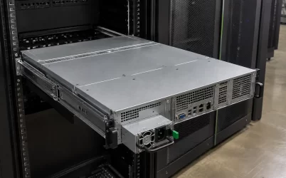
An open-frame board transfers mechanical, thermal, accessibility, and part of the EMC integration work to the host equipment. The published rating applies only under the manufacturer’s stated conditions. The installed system must reproduce the required airflow, ambient limits, orientation, clearance, and mounting arrangement rather than assuming that unrestricted room air represents the final enclosure.
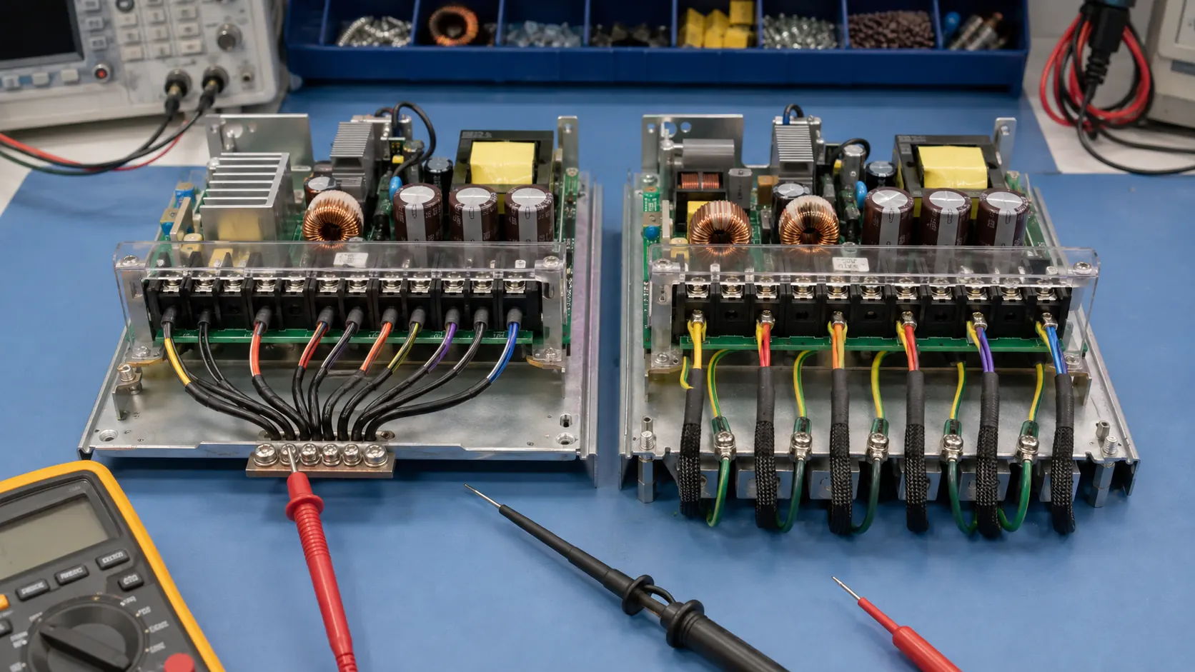
Four-output loading can concentrate heat unevenly. Two candidates with the same total delivered power may stress different rectifiers, magnetics, connectors, or PCB regions because their rail allocations differ. A thermal review should therefore use the actual simultaneous rail state, not just total watts. Verify that airflow reaches the intended components without being blocked by harnesses, covers, filters, adjacent boards, or stagnant pockets.
The host enclosure also has to control access to hazardous energy, preserve required spacing around the exposed board, provide appropriate protective-earth and mounting provisions, and address system-level emissions and immunity. Input protection, disconnecting means, fusing, wiring, and touch protection must follow the exact product documentation and the final equipment’s applicable safety requirements. An open-frame approval or specification does not remove the final-equipment integrator’s responsibilities.
Decide whether four native outputs simplify the architecture
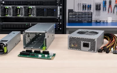
A native quad-output AC-DC supply is not automatically preferable to a simpler AC-DC front end followed by downstream conversion. The better architecture is the one that gives the required loads clear regulation, sequencing, protection, thermal, and sourcing boundaries.
| Decision factor | Native quad-output AC-DC board | Main AC-DC rail plus downstream converters |
|---|---|---|
| Rail generation | Four outputs originate from one power-supply assembly | One primary bus feeds local DC-DC stages |
| Regulation dependency | May include cross-regulated or grouped outputs; exact model documentation controls | Local regulation can be assigned to each load zone |
| Sequencing | Depends on native rise behavior and any host-side switching | Enable controls may provide more explicit sequencing |
| Fault boundary | A fault may affect multiple outputs according to the supply design | Local stages can separate some faults, but the main bus remains shared |
| Conversion stages | Can reduce the number of downstream converters | Adds conversion stages, components, heat, and potential EMI sources |
| Voltage customization | Limited to documented variants and adjustment provisions | Broader rail combinations may be practical from a standard bus |
| Sourcing impact | One specialized supply provides the complete voltage set | A common main supply may be paired with separately sourced converters |
Downstream conversion is especially worth considering when one auxiliary voltage has unusual tolerance, sequencing, isolation, transient, or availability requirements that a catalog quad-output model cannot satisfy cleanly. In that architecture, the input behavior of each open-frame DC-DC converter must be matched to the real main bus during startup, normal operation, disturbances, and shutdown.
The alternative is not free. Additional converters create their own losses, thermal paths, switching noise, control interfaces, mounting needs, and failure modes. Conversely, a specialized native four-output board can create a concentrated sourcing dependency. Lifecycle availability, acceptable substitutions, and the effort required to requalify a changed voltage combination belong in the architecture comparison.
Send suppliers the completed matrix, not four voltage labels. Require the manufacturer, exact model and variant, datasheet revision, input and cooling conditions, connector arrangement, included hardware, and substitution controls.
- V1–V4 load-terminal voltage, tolerance, continuous and transient current, and simultaneous states.
- Exact individual, grouped, total-power, minimum-load, and derating limits.
- Startup, shutdown, pre-bias, recovery, and permitted cross-rail disturbance.
- Return, grounding, sensing, trim, cooling, orientation, and enclosure assumptions.
- Overload, short-circuit, disconnection, and backfeed behavior for each rail.
Verify simultaneous startup, delayed enable, maximum coincident demand, light-load combinations, shutdown, and authorized faults. Measure at the loads where wiring drop matters, and observe all four rails together for sequencing or cross-regulation.
Approve a quad output open frame power supply only as an exact variant whose documented envelope covers all loads and dependencies. Otherwise, compare a main AC-DC rail with downstream conversion.