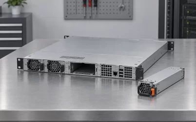
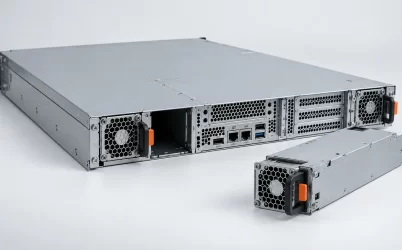
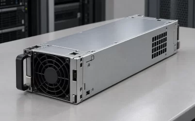
A 1U CRPS power distribution board is not identified by the rack height alone. It must sit at the end of the removable PSU’s guided travel, hold the mating connector in the correct position, and send power and control connections onward without colliding with the fan wall, motherboard, rear I/O, or the lid. A board sold for a 1U chassis may serve one CRPS module or a pair; the word CRPS does not make the assembly redundant. The useful question is whether the complete board, its carrier and its output wiring occupy the right space in the particular chassis.
The board belongs at a mechanical datum, not in the first open pocket
Consider the power bay from the rear of a 1U server. A module enters through an opening, follows guides, and stops when its output edge has engaged the mating connector. The connector is mounted on a board or assembly that must be supported by the chassis. That board is usually concealed in a product photograph focused on the removable PSU, yet its position determines whether the module seats at all. Moving it a few millimeters to clear a component can alter connector engagement, latch position, or the relationship between the module fan and the chassis air path.
The mechanical reference is not simply the board’s width and length. It includes the cage or guide-rail datums, connector centerline, insertion direction, stop position, mounting-hole pattern, PCB thickness where relevant, and the clearance around populated components. A bare PCB dimensions drawing answers only part of the problem. A complete assembly drawing shows how the connector is held relative to the module while the server is assembled and during repeated service operations. If the mating connector is allowed to become the structural stop or the rail alignment tool, its electrical contacts may see mechanical loading they were not intended to carry.
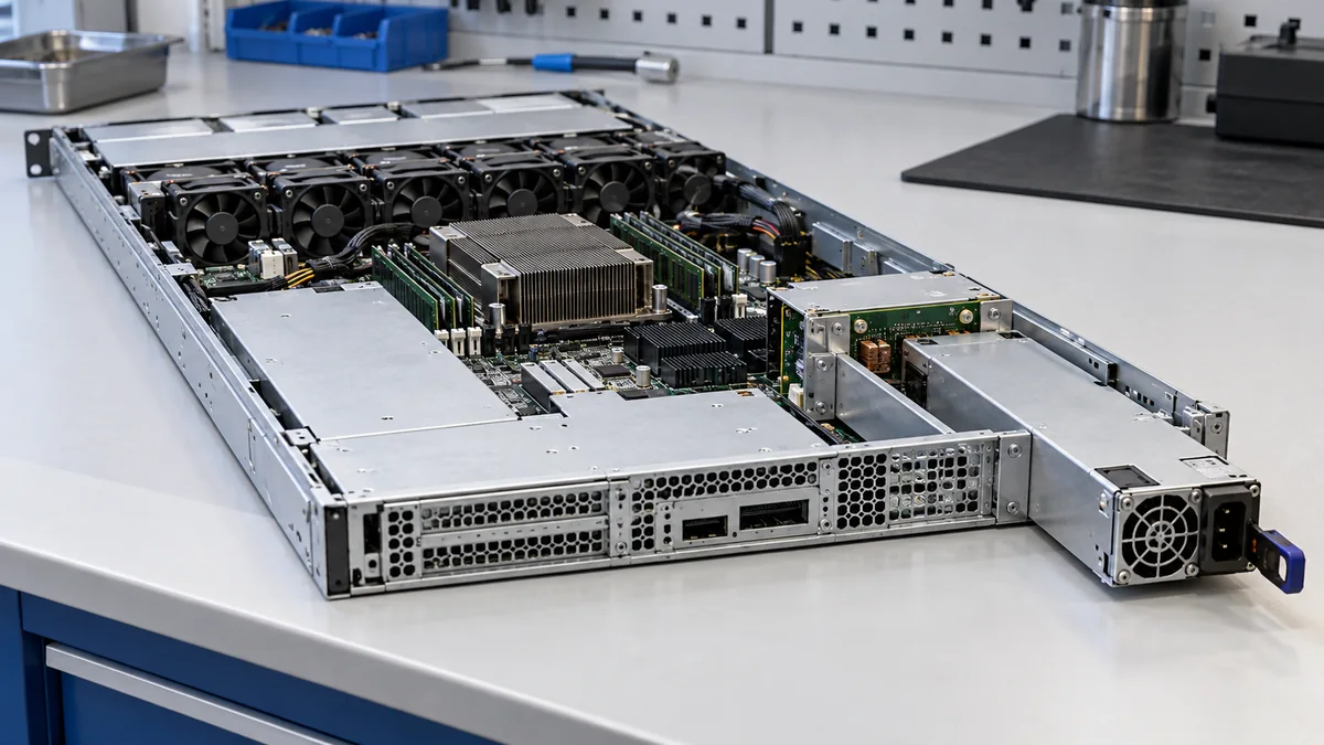
Height is particularly unforgiving. The external rack-unit designation does not equal free internal component height. The lid, base metal, insulating clearance, connector body, mounting hardware, solder joints, and any bracket all consume part of that envelope. A board that clears the chassis with no module installed may still interfere with the module during insertion or with its latch after closure. Even the direction of a connector’s cable exit can decide whether the lid closes without pressing on a harness.
A one-module PDB and a two-module PDB solve different space problems
Search results for “1U CRPS power distribution board” mix single-slot adapters and two-slot redundant assemblies. That is not a trivial product-option difference. A single-slot board needs one module mating position and may route output through a fixed harness. A two-slot assembly needs two guided module paths, two mating positions, and a shared distribution arrangement. The second position consumes rear-panel width, changes the board’s outline, and may move output connections deeper into the chassis. Its electrical design may also include source isolation and current sharing, but those functions cannot be inferred merely from the number of connector openings.
FSP’s published FSP-PH51A CRPS PDB datasheet is a useful counterexample to the assumption that every CRPS board is a two-module redundant backplane. It explicitly describes a board designed for a 1U chassis that supports a single CRPS module and a fixed wire harness. The documented board dimensions apply to that model only. They are not a standard envelope for other 1U boards, and the sheet does not make the board a drop-in replacement for an unrelated server’s PDB.
For a compact server that needs just one removable supply, a single-slot architecture may avoid occupying width that the platform needs for network ports, storage interfaces, expansion, or fans. It does not preserve operation after that sole module fails. A two-slot architecture can support a defined redundant operating mode only when the selected modules, PDB, host, and load policy provide that behavior. The geometric choice is therefore tied to the service requirement, not to a slogan about CRPS. A one-slot board should not be rejected solely because the acronym contains the word “redundant”; a two-slot board should not be credited with protected capacity solely because it fits two supplies.
Board orientation matters as much as slot count. Two supplies may sit side by side or use another supported arrangement, and their fan openings, handles, inlets, and blind-mate contacts must remain accessible. A design that packs two modules into the rear panel but blocks one extraction handle with rack cabling has not preserved the service advantage of removable supplies. If the chassis has only one module opening, fitting a two-slot PDB is not a board substitution. It changes the rear-panel cutout, guides, mounting structure, and likely the load distribution and firmware behavior.
The PSU connector position controls the rest of the PCB
A PDB can have generous copper area on paper and still be impossible to place in a 1U host. The PSU receptacle must meet the module at its guided endpoint. From that fixed location, the designer has to accommodate the main-current route, returns, standby and control paths, protection or combining components where present, mounting holes, and downstream connectors. The board’s outline is shaped by those relationships rather than by a universal 1U rectangle.
The available board area may be interrupted by a chassis stiffener, fan-wall frame, motherboard edge, or storage cage. A designer may rotate a downstream connector or split a harness to regain space, but each change affects cable bend, insertion access, and the current path. Low-profile connectors can help height while increasing footprint. A vertical connector may save board area but place a cable directly under the lid. A right-angle output may clear the lid yet require more depth behind the PSU. None of these alternatives is inherently correct; the installed geometry and electrical rating of the exact components determine whether it works.
Contact loading becomes a practical reason to preserve mechanical alignment. A high-current connection depends on its intended contact geometry and insertion depth. Partial mating can concentrate current and heat, while a board flexed by an output harness can change the way a receptacle meets the module. The board should have supports appropriate to its connector forces and cable loads. A test that confirms continuity on a bench does not prove that repeated PSU insertion in the finished rack will maintain that contact position.
The PDB also needs a deliberate return path. At high current, the positive and return paths are not interchangeable decorative traces; each must have sufficient conductor and connection capacity under the allowed operating states. A long detour around a mounting hole can add loss or create a localized warm region. These are electrical-layout questions, and Powernexu’s CRPS distribution-board design explanation covers them in depth. For this 1U question, the important point is spatial: the current path has to fit around real mechanical obstructions without turning into an unsupported assumption about board rating.
Downstream cable exits can defeat an otherwise clean fit
After the CRPS module has mated, the PDB still has to reach the host. A board with a fixed wire harness may route power toward the motherboard and auxiliary loads; another may expose sockets or a bus connection. A photograph that shows the board alone often omits the installed bend radius, connector backshell, retention feature, and space needed to disconnect the harness. In a 1U enclosure, those features can occupy the corridor between the PDB and the fan wall.
Trace the cable in three states: installed with the lid closed, undergoing module service, and being assembled or disconnected by a technician. The operating state shows whether the harness rests against a fan, heatsink, sharp sheet-metal edge, or airflow opening. The service state shows whether withdrawing the PSU pulls on the board or disturbs a neighboring connector. The assembly state shows whether the output connector can actually be reached after the motherboard, riser, and fan carrier are installed. A cable route drawn as a thin line on a top-view diagram hides all three problems.
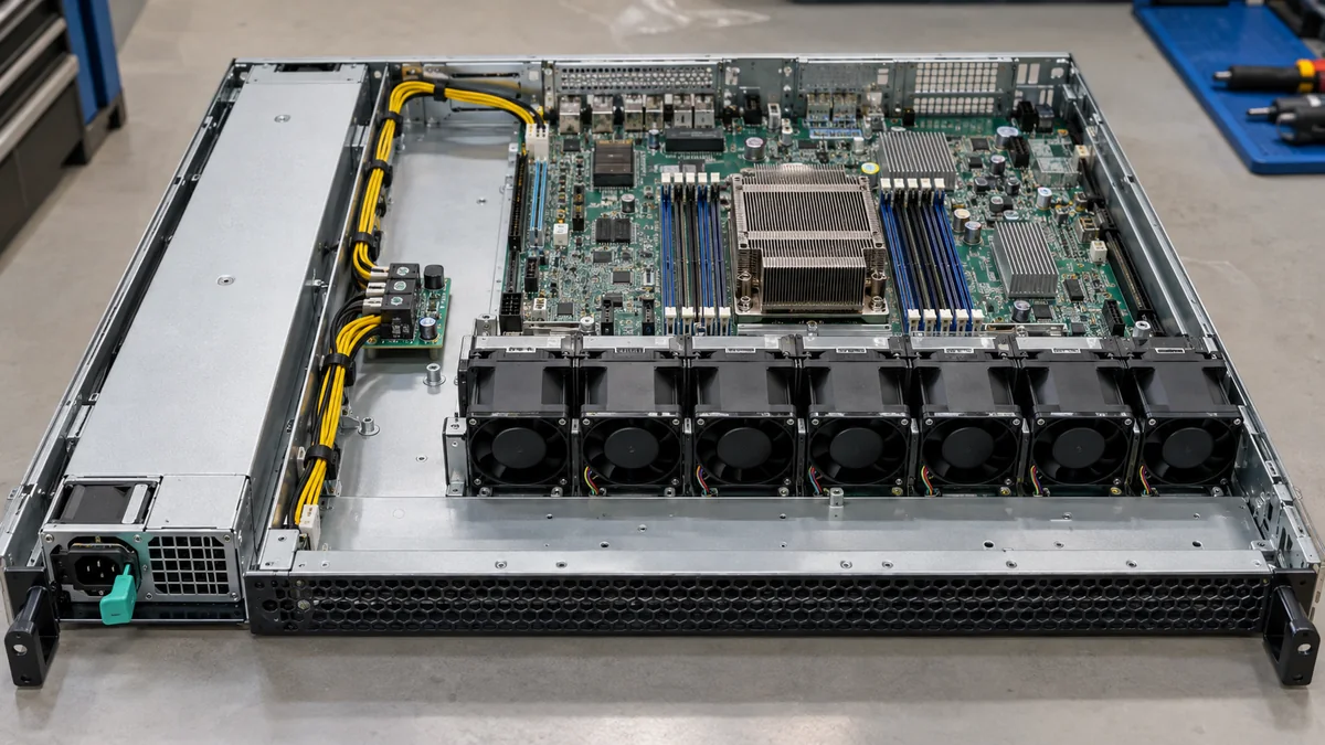
Do not infer the output architecture from the CRPS module’s label. A module may supply a primary DC bus while the PDB or other boards create or distribute auxiliary rails. The harness and connector population of one commercial PDB do not define another. A 1U adaptation needs the specific motherboard and load-board requirements, but those details should be taken from their documentation. Replacing a PDB with a board whose wires merely reach the motherboard can still fail because a required standby, enable, status, or management path is absent.
Air and service clearances share the same thin volume
The PDB is often located near the rear power modules, where warm air, small fans, connectors, and cables converge. Its components and harness must not form an unintended wall across the host’s air path. Conversely, putting the board into a high-velocity passage does not automatically cool its hottest connection. The local air that reaches a connector can be warmer than air measured at the rack inlet, and a solid cage or bundled cable can shelter one area from flow.
A board mounted just behind a module may see a different thermal condition after a PSU is removed. The empty bay can become a bypass route unless the chassis provides an appropriate blank or seal. That question belongs to the actual server airflow design; it cannot be answered from a bare PDB specification. Likewise, the PDB’s environmental rating and the CRPS module’s rating are separate documents. If either component has a lower allowable condition in the installed location, the assembly must operate within that limit.
Maintenance can conflict with cooling. A technician needs to see and grip the module latch at the rear, and the module needs a straight path out of the bay. Adding a bracket to secure the PDB may preserve connector alignment but intrude into the module extraction path. Moving the bracket can create a board-support problem. The design has to satisfy both conditions at once: repeatable mating and practical removal with the server in its intended rack position. Neither a successful bench insertion nor a closed-lid photograph proves service access.
Read “designed for 1U” as a host-specific proposition
A manufacturer’s 1U claim describes the chassis class a board was designed around; it does not certify fit in every server of that height. The board’s own drawing should be read alongside its intended module drawing, cage and rail arrangement, chassis envelope, and output-harness information. A product sheet can establish that a particular PDB supports a particular module population and has a stated board outline. It cannot establish that a different server has the same mounting coordinates, front-to-rear air path, output connector needs, or service opening.
For a new 1U design, the useful deliverable is a common assembly model in which the PDB, cage, selected CRPS module, chassis metal, fan wall, motherboard, and output route are all present. The model can expose collisions before the board outline is committed, while the exact electrical design remains tied to supported component documents and testing. If a single-slot board is adequate, its compactness can preserve space for other hardware. If a two-slot architecture is necessary, that width and service envelope must be reserved deliberately rather than added after the rear panel is full.
That is what the phrase “1U CRPS power distribution board” should communicate: not a universal board shape, but a specific mating and distribution assembly that can be installed, cooled, connected, and serviced inside one defined 1U server. The board is suitable only when all of those physical relationships exist in the target chassis.