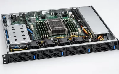
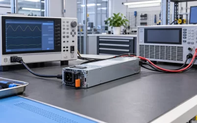
A “3U server power supply” is not a single standardized object. The phrase can mean a PSU intended for a server chassis that occupies three rack units, a physically tall industrial supply sold for 3U cases, or a 3U CompactPCI plug-in module. Those products can have entirely different mounting, connectors, outputs, and replacement methods. For an existing rack server, identify the chassis and installed power assembly before choosing a wattage or brand. A 3U case may accept a smaller ATX, 2U-style, or proprietary redundant unit; the rack height alone does not tell you which one. This distinction is the fastest way to avoid ordering a technically impressive PSU that cannot be installed.
Three rack units describe the chassis, not its PSU cavity
In a rackmount server, 3U describes the enclosure height. It does not require the power supply itself to fill that height. The chassis designer may allocate the extra space to drive bays, expansion cards, a larger fan wall, or easier service access while still using a relatively compact power assembly. Other 3U systems do use a tall cabled PSU or a rear redundant cage. Both are valid approaches, and neither can be inferred from the label on the front of the rack.
A common replacement mistake is to search for “3U PSU” when a server powers down and select an item whose dimensions look close to the chassis height. That ignores the rear-panel cutout, mounting holes, cable exit, fan direction, and internal clearance. A unit can fit within the outer envelope yet collide with a drive backplane or leave its AC inlet inaccessible. A smaller supply can be correct if it matches the original bracket and wiring. The correct physical question is: what volume and interface did this specific chassis reserve for its power subsystem?
Begin with the chassis model and revision, not the failed unit alone. The server manual or bill of materials may list several power options for the same case, including single fixed and redundant assemblies. Remove assumptions about an empty bay: a second opening does not prove that an arbitrary spare can be installed there. Photograph the original PSU, its label, rear opening, mounting flange, output connectors, and the path of every cable or bus connection. Those observations establish whether the purchase is one converter, a complete assembly, or a chassis-specific spare.
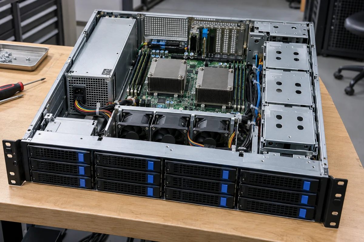
Depth is often the more difficult dimension than height. A 3U storage server can fill its front half with drive carriers and its middle with fans and a backplane. The PSU may be at the rear, with only a short corridor left for cables. A supply that is 20 mm longer than the original may compress the harness into the fan wall even though there is ample vertical room. Conversely, a larger three-dimensional envelope might be acceptable in a relatively empty industrial chassis. The published chassis drawing, not a generic 3U category, resolves the difference.
“3U” can also name an unrelated CompactPCI module
Search results for this phrase often include 3U CompactPCI or similar modular industrial computing supplies. In that context, 3U is a board or plug-in module form factor, commonly paired with a defined width and a backplane connector. It is not the same thing as a rack server’s 3U enclosure height. A CompactPCI unit is designed to slide into a compatible card cage and mate with its own power interface. A conventional server PSU may have fixed cables or a completely different blind-mate connector.
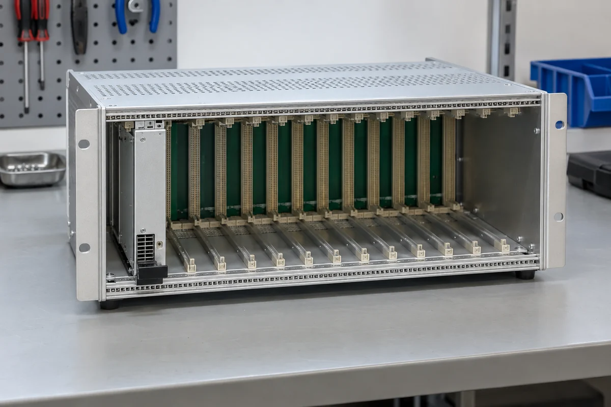
For example, Kontron’s official 3U CompactPCI supply page identifies a particular 3U × 8HP module with a P47 connector and defined hot-swap and redundancy functions. That verified example illustrates the terminology collision. It does not imply that a rackmount 3U server accepts that module, nor that every CompactPCI supply has the same output or connector. A buyer searching by height alone could receive a module that is correct within an industrial card cage yet useless for the server on the bench.
Different meanings also create misleading compatibility statements. “Hot-swappable” on a CompactPCI datasheet refers to operation in an appropriately designed card cage. It cannot be transferred to a fixed cabled PSU in a rack server. “Redundant” similarly requires the specific backplane and control arrangement for that module family. Treat form-factor language as a clue to the intended system, then use the full interface definition to decide whether the candidate belongs there.
When a listing says “3U server PSU,” ask whether 3U names the host, the PSU body, or a plug-in card format. The answer changes what other data matters. For a rack server, chassis and approved assembly identifiers lead. For a CompactPCI module, the card-cage standard, slot width, depth, backplane connector, and voltage rails lead. Mixing those records because the same numeral appears on both products is a category error, not a small fitment risk.
The rear panel reveals the replacement architecture
The rear of the server provides a practical architectural map. A single rectangular AC inlet integrated into a larger PSU housing often points to a fixed or individually mounted supply. Two narrow extractable handles with separate AC connections suggest removable modules in a cage, although their redundancy mode still must be confirmed. A full assembly may include the modules, a metal carrier, and a power distribution board behind the rear openings. The visual layout tells you where to look in the manual, but it is not a substitute for the approved-parts list.
If the system has a fixed cabled supply, power reaches the motherboard, processor inputs, drives, and accessories through harness branches. The replacement must provide the required connector families, pin assignments, rail capacities, and cable reach. Familiar connector shells do not rule out a proprietary wiring convention. In a compact storage chassis, moving a cable exit from one side to the other may place the entire bundle across a fan or service opening. A nominally stronger unit can therefore be a worse replacement than the exact rated original.
If the server uses redundant cartridges, the converter modules dock into a cage or power distribution board. Here the mating geometry and host-approved part relationship dominate. A module from another 3U server may slide partway in and still fail to engage its connector or latch correctly. The distribution board may handle output combining, standby paths, monitoring, and downstream power routing. Some parts listings show only the removable converter, while others show the cage or full assembly. Clarify what is physically included before assuming a quotation will restore the server.

Airflow direction belongs in the same rear-panel inspection. The server may expect a front-to-rear flow through the PSU, or another arrangement that matches its fan system. A replacement with reversed flow can return warm air to the chassis or oppose the fan wall. A drive-dense 3U case may have more vertical room than a 1U server but also much greater flow resistance. PSU thermal limits apply to the air the unit actually receives inside that case, not merely the data-center room temperature.
Wattage must serve the installed load and failure mode
Once the mechanical and electrical family is known, the output rating can be evaluated. The server’s CPU, memory, drives, expansion cards, fans, and management functions create different demands. Storage drives can have a startup behavior unlike their steady running power; accelerators can add transient demand. A PSU with adequate total watts may still lack a required rail or connector branch. An old supply’s number on the label is a useful lead, but a changed server configuration can alter the required envelope.
For a single-PSU 3U host, the chosen unit must carry the supported workload by itself under the actual AC input, temperature, and airflow conditions. If the chassis uses a 1+1 redundant pair, one surviving module must carry the load after the other is removed or fails. Two equal ratings should not be added and presented as protected capacity. Some multi-PSU systems deliberately use the combined output in a non-redundant mode; the host power policy then determines what happens after losing one unit. These distinctions are properties of the platform configuration, not of the 3U label.
Consider a hypothetical storage server that requires 850W DC at its heaviest supported operating state and has two 1,000W modules. One module appears large enough for 1+1 operation in simple arithmetic, but the conclusion still depends on the exact module’s usable output at the deployed input, the PDB’s current paths, thermal conditions, and the chassis power policy. If the system instead uses one fixed 1,000W PSU, there is no second module to carry the load after that unit fails. The same 3U server height and nominal wattage produce different availability behavior.
Input voltage can also make a printed maximum conditional. Some high-output server modules deliver a lower continuous rating on lower AC voltage or require a high-line feed for full output. The site’s rack PDU, cord, outlet, and branch circuit must support the surviving or sole module’s AC demand. DC output watts are not equal to AC input watts because conversion has losses. For a replacement, read the precise product documentation rather than assuming that a wide input range guarantees full wattage across the range.
A spare and a new 3U build need different evidence
For a failed server, preserving the intended host architecture is the priority. The chassis model, installed PSU label, approved alternate-part record, and any power-board identifier should converge on the replacement. If the original spare is discontinued, a supplier should identify the documented successor for that exact host. Changing to an unrelated higher-wattage unit may trigger connector, airflow, management, or firmware incompatibility. A spare is successful when it restores the supported operating state, not when its catalog headline sounds more powerful.
A new 3U system design allows more choice. An integrator might allocate the rear panel to a single cabled supply, a redundant CRPS cage, or another approved architecture. That decision should follow the mechanical map: drive count and backplane location, fan wall, expansion slots, rear I/O, cable channels, and service access. A 3U height can offer useful packaging freedom, but its extra space is not automatically available at the PSU location. The electrical distribution arrangement must be designed along with the selected modules.
Product links should reflect this specificity. Powernexu lists server and CRPS supplies in several wattages, but none becomes a verified replacement for an unnamed 3U host merely by fitting below three rack units. A module page is appropriate only after the server’s voltage, interface, cage, current, and cooling requirements are established. For a new platform, product families can be compared as components of a planned subsystem; for a field repair, the host’s supported assembly list should remain the source of truth.
The phrase “3U server power supply” is therefore best treated as the start of identification, not as a finished specification. First resolve whether 3U describes the rack chassis or a CompactPCI module. Then identify the host’s actual power architecture from its rear opening, approved parts, wiring, and operating policy. Only after that do wattage and efficiency become useful filters. That sequence prevents a form-factor collision from becoming a wasted order or an unsafe fitment experiment.