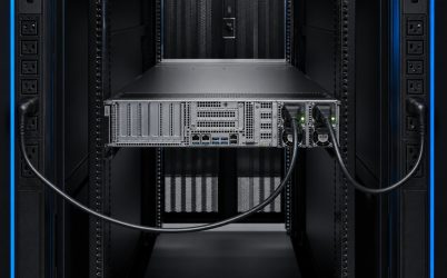
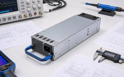
A redundant hot swap power supply lets an authorized PSU module be removed and replaced while the supported system remains energized. Achieving that result requires two separate capabilities. Redundancy provides another power path with enough capacity for the active load; hot-swap design controls electrical isolation, connector sequencing, inrush, signals, and management during live service. A second module and a handle are not sufficient evidence. The exact PSU, PDB, connector, chassis, firmware, and service procedure must be designed and validated as one system.
Quick answer: confirm the survivor before touching a live module
Before replacement, identify the failed bay, confirm that the other PSU and its upstream feed are healthy, and verify that the surviving module can support current and anticipated transient load at the deployed input and temperature. Follow the platform’s documented hot-swap procedure and use an approved replacement. During qualification, monitor the shared DC bus while each module is removed and inserted, verify inrush and contact sequencing, check current sharing after recovery, and confirm BMC alarms and event logs. If the platform documentation does not explicitly permit live service, power down rather than inferring hot-swap support from physical removability.
Redundant and hot swappable answer different questions
Redundancy asks whether another path can maintain required output after a defined failure. In a 1+1 design, either module must support the permitted system load under actual input, thermal, and airflow conditions. Hot swap asks whether a module can be disconnected and reconnected while the bus is live without unsafe arcing, excessive inrush, bus collapse, corrupted control state, or damage.
A system can be redundant but require shutdown for replacement, or it can have a hot-pluggable component without enough remaining capacity to keep the load running. Product documentation should state both capabilities and their conditions. Operators also need the maximum load at which redundancy is preserved; total installed wattage can be misleading when one module must carry everything during service.
Define the failure set and upstream power paths
Two PSUs may protect against an internal module failure. If both connect to the same rack PDU or branch circuit, that source remains a common point. A true A/B scheme routes the modules through appropriately independent cords, PDUs, branches, and upstream infrastructure according to the facility design. Draw the complete paths and identify every shared element, including the server PDB and DC bus.
Hot swap temporarily leaves the server on one path. Maintenance risk is therefore higher if the surviving path has an unresolved alarm, overloaded connector, marginal input, or shared upstream dependency. Monitoring and pre-service checks should distinguish an input loss from an internal PSU fault so the technician replaces the correct component.
Surviving-module capacity includes transient demand
Use the maximum allowed load after considering low-line derating, inlet temperature, altitude, and airflow. The server’s processor, memory, drive, fan, and accelerator loads can change faster than slow management telemetry shows. A single PSU must support credible excursions immediately after the companion is removed. The PDB, connectors, and cables must also carry the transferred current.
Average power is therefore not a sufficient sizing input. Characterize sustained maximum, peak magnitude, slew rate, duration, repetition, and permitted bus deviation. Supported firmware power caps can help manage a platform, but only if their response and limits are documented and coordinated with electrical hold-up. They do not replace instantaneous capacity by assumption.
Contact sequencing makes live insertion controlled
Hot-swap connectors can use different contact lengths so protective or chassis connection, returns, presence or precharge functions, communication, and main power engage in an intentional order. During removal, the reverse sequence helps disable power transfer before high-current contacts separate. The exact arrangement is defined by the interface; it must not be guessed from a similar connector.
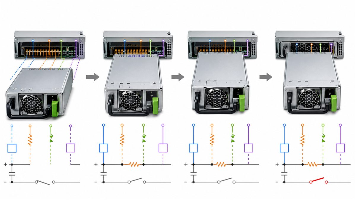
Inrush control protects the connector and shared bus
An incoming PSU contains capacitance that may initially appear as a low impedance. If connected directly to a live source or shared output, charging current can cause arcing, contact damage, a bus dip, or a protection trip. Precharge paths, resistors, controlled MOSFETs, soft-start circuits, and staged enable signals are common design approaches, but their location and behavior vary.
Measure incoming current and shared-bus voltage during insertion at input and temperature extremes. The healthy module must remain within its output and transient limits. Repeat insertion to check consistency and thermal effects. Adding more capacitance without analysis can worsen inrush or interact with the control loop, so any PDB or load-capacitance change should trigger review.
ORing prevents a failed module from dragging down the bus
Redundant outputs need reverse-current isolation. Diodes or controlled MOSFET stages may perform the ORing function in the PSU, on the PDB, or through a coordinated architecture. They must block current into an unpowered or faulted module and withstand the transition when one path disappears. Their resistance and switching behavior affect voltage drop, heat, and rail disturbance.
Analyze both open and short failure modes. A faulted output should be isolated before it collapses the common bus within the defined system tolerance. Protection coordination among the PSU, ORing stage, PDB, and downstream branches determines whether a local fault remains local. Hot-swap permission should be based on this coordinated design, not solely on a connector’s mechanical rating.
Current sharing must recover after replacement
When two active modules are healthy, share control distributes output current. During extraction, the survivor takes the load; after insertion and startup, the new module joins the bus and sharing stabilizes. Observe each module’s current and temperature through this transition. An imbalance that persists can overheat one path even while total server power remains below the pair’s combined rating.
Some platforms intentionally place one PSU in standby or use an efficiency mode. Such strategies require compatible module firmware, PDB logic, and BMC control. The newly inserted supply must enter the correct state and be ready to assume load on demand. Mixing models or revisions can disrupt sharing or create management alarms even when both outputs are nominally equal.
Standby, enable, and power-good timing coordinate the event
A hot-swap module may provide standby power and communication before enabling the main output. Presence detection tells the BMC that a module is being inserted. Enable and power-good signals mark stages of initialization. Timing, polarity, logic levels, and default states are specific to the interface. The host must tolerate signal changes without unintended resets or false fault clearing.
Use an oscilloscope or logic capture to correlate main bus, standby rail, enable, power-good, present, and current during insertion and removal. Verify cold and warm conditions and both PSU bays. A successful front-panel LED is not enough if the BMC logs communication errors or the main rail experiences an out-of-limit transient.
PMBus and BMC behavior guide safe service
Where supported, management data can identify input status, output current, temperature, fan speed, warnings, faults, manufacturer information, and module presence. Exact PMBus command coverage and accuracy vary. The BMC may require approved identity or firmware data and can reject an otherwise electrically functional replacement.
Test the full alert chain: local LED, BMC state, event log, remote monitoring, notification, acknowledgement, and clearance after repair. Loss of redundancy should create a timely actionable alarm because the server can continue running and hide the failed path. Verify bus recovery when a module disappears mid-transaction or is inserted with a different address state.
Thermal and airflow conditions change with an empty bay
Removing a module changes both heat generation and chassis airflow. The remaining PSU produces more loss as its output rises and may increase fan speed. The open bay can create a low-resistance bypass path or allow exhaust recirculation. Platforms may require a blanking device if a bay remains empty beyond the immediate service operation.
Measure the surviving PSU, connector, PDB isolation devices, and nearby server components at sustained maximum redundant load. Test high inlet temperature and altitude where relevant. The approved maintenance window should account for thermal behavior, not only electrical capacity.
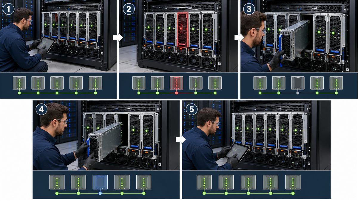
A controlled field replacement workflow
- Confirm the alert, physical bay, and whether the fault is in the input feed, cord, PSU, or PDB.
- Verify the other module is healthy and the current load remains below the validated redundant limit.
- Check that the replacement is an approved exact model or documented compatible alternative.
- Follow site electrical-safety rules and the server manufacturer’s live-service procedure.
- Release and remove only the identified module without disturbing the healthy cord or neighboring cables.
- Inspect the bay and connector for damage, contamination, discoloration, or obstruction.
- Insert and latch the replacement fully without forcing it or defeating connector keying.
- Confirm input, standby, main output, power-good, current sharing, fan, telemetry, and cleared alarms.
- Record the part number, revision, fault, replacement, and relevant event-log entries.
This sequence is a general engineering framework. The product-specific manual takes priority because connector, indicator, latch, and safety procedures differ. If the healthy path is overloaded or unstable, reduce load or arrange an approved shutdown instead of proceeding with a live swap.
Compatibility of the replacement is multidimensional
A visually similar module may differ in depth, guide features, connector keying, pinout, output rail, standby current, enable timing, current sharing, PMBus identity, airflow direction, full-power input range, or firmware. A higher wattage does not make those differences disappear. Follow the platform’s approved-parts policy and retain configuration records.
When a substitution is unavoidable, compare exact drawings and interface documents, then run the same qualification used for the original pair. Mixing modules can create unequal sharing or host warnings. Powernexu’s CRPS compatibility guide provides a structured review for common redundant form factors.
Qualification must reproduce service transitions
- Run each module alone at the maximum permitted redundant load.
- Interrupt each AC input separately and verify upstream path independence.
- Remove and insert both modules at light, typical, and high supported load.
- Capture shared-bus voltage, module currents, inrush, and control timing.
- Verify fault isolation, reverse current, protection, and recovery.
- Measure temperatures in normal, degraded, and empty-bay states.
- Check PMBus data, BMC acceptance, LEDs, event logs, and remote alerts.
- Repeat critical transitions across temperature and representative production samples.
The acceptance limits should come from the server, PSU, and PDB specifications. Store the tested module, hardware, firmware, BMC, and chassis revisions. Requalify after changes that affect the electrical interface, airflow, management policy, or workload envelope.
Operational practices keep hot swap safe and useful
Maintain compatible spares, clear A/B feed labels, clean service access, and trained procedures. Monitor loss of redundancy as a priority event. Avoid leaving a failed module or empty bay in place longer than the platform permits. Periodically verify that alerts reach the responsible team and that rack changes have not moved both PSU cords to one source.
Hot swap is valuable because it converts a hardware failure into a planned service action without workload interruption. That value exists only when capacity, isolation, sequencing, cooling, compatibility, monitoring, and human procedure remain aligned. The related hot swap server power supply design article provides additional platform context.
Questions about redundant hot-swap systems
Can any removable PSU be replaced while powered?
No. Live replacement is appropriate only when the platform documentation explicitly supports it and the system remains within its redundant load limit. A removable handle does not prove electrical hot-swap capability.
What happens if the wrong module is removed?
If the supposedly failed module was actually healthy and the other path cannot support the load, the server can shut down. Confirm bay identity through multiple indicators and verify the surviving path before release.
Can a hot swap cause a brief voltage dip?
A real system can experience a controlled transient, but it must remain within the server bus limits so downstream converters continue operating. Qualification measures that disturbance at representative loads and temperatures.
Should both redundant PSUs use separate electrical feeds?
Use appropriately independent A and B feeds when the availability requirement includes tolerance of PDU, branch, or upstream source loss. One shared feed may still protect against certain PSU failures, but it is a narrower redundancy design.