A rackmount server power supply is constrained by the server chassis before electrical selection even begins. A 1U system offers little height for fans, connectors, and extraction hardware; a 2U or 4U chassis provides more layout freedom but may allocate rear-panel space to expansion slots, storage, or networking. The PSU must fit the bay, align with the power distribution board, support the actual workload at the available input voltage, move air in the chassis direction, and remain serviceable after the server is installed in a rack. This article treats the PSU as part of the rackmount layout rather than as a standalone wattage component.
Start at the rear panel, not the wattage label
Rear-panel real estate determines how many PSU bays can be installed, whether modules sit horizontally or vertically, and how much clearance remains for PCIe cards, network ports, management interfaces, and cable bend radius. In a shallow chassis, PSU depth can conflict with fans, the motherboard, or a midplane. In a dense 1U design, a few millimeters can determine whether a module can be extracted without removing the server. The mechanical drawing, connector datum, guide features, latch travel, and handle envelope deserve the same attention as output power.
Rack installation adds another layer. Power cords must reach the intended rack PDU without blocking exhaust or interfering with sliding rails. A module should be removable while adjacent network and storage cables remain connected. If the rack is close to a wall or rear door, allow room for cord retention and the full extraction path. A PSU that fits on a bench can still be impractical in the deployed cabinet.
How chassis height changes the power design
| Chassis | Typical power-design pressure | Integration focus |
|---|---|---|
| 1U | Very limited height and narrow airflow channels | Module height, small high-speed fans, connector density, extraction clearance |
| 2U | Competition with expansion and storage zones | PSU arrangement, fan wall, cable routing, rear I/O allocation |
| 4U and larger | Higher total load and more configuration variation | Multiple modules, distribution capacity, airflow balance, service access |
These are design tendencies, not universal specifications. A particular server can use a proprietary arrangement. The useful decision is to map the actual component zones: PSU bay, PDB, fans, processors, memory, accelerators, storage backplane, expansion cards, and cable channels. That map reveals whether the planned power module supports rather than obstructs the thermal and service strategy.
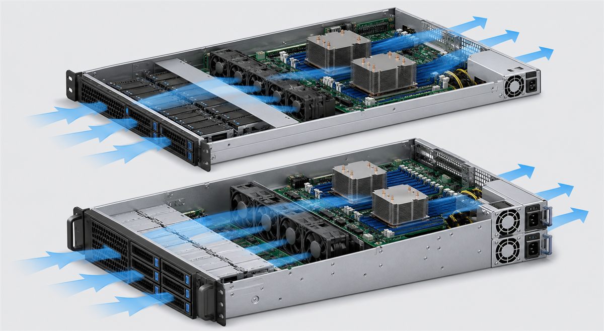
Airflow direction is a compatibility requirement
Most rack servers are designed around front-to-rear airflow, but the PSU fan and grille must cooperate with the complete pressure path. A reverse-airflow module can recirculate hot air or oppose chassis fans. Even with the correct direction, a module with different impedance can change how much air reaches processors, memory, and accelerators. Fan policy may also depend on communication between the PSU and the baseboard management controller.
Evaluate the server at the maximum intended inlet temperature and altitude. The PSU output may derate as temperature rises or air density falls. An empty redundant bay can create an airflow bypass, while the surviving module can run hotter because it carries the full load. Blanking hardware, fan-speed response, and repair time therefore influence the usable power envelope.
Convert the workload into a chassis power envelope
Build the load profile from the configured server rather than the theoretical maximum of every available option. Include processors, memory, storage, network adapters, accelerators, fans, motherboard conversion losses, and standby circuits. Separate sustained demand from boot, fan ramp, drive spin-up, accelerator excursions, and other transient events. The PSU and PDB must keep the main bus within limits during the fastest credible transitions.
Capacity depends on input voltage. High-power modules may deliver their largest output only over a higher-voltage input range. A laboratory test from a common low-voltage receptacle may therefore produce less usable output than the data-center installation—or the reverse assumption may lead to an invalid lab setup. Record the rack PDU voltage, inlet and cord rating, branch capacity, and low-line derating.
The PDB decides whether a module is truly compatible
The rackmount PSU normally mates with a distribution board through a blind-mate connector. Matching enclosure shape does not establish the same pinout, output rail, standby supply, remote sense, enable, power-good, current share, or PMBus behavior. The PDB also has its own current, connector, copper, isolation, and thermal limits. Installing a larger PSU does not increase those limits.
Compare the exact module and PDB documents contact by contact. Mechanical insertion should be tested without forcing the connector. Electrical commissioning should begin under controlled conditions before full load is applied. Host firmware may identify the module and restrict operation if its identity or telemetry is unsupported.
Redundancy changes rack cabling and usable capacity
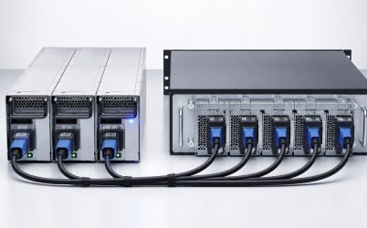
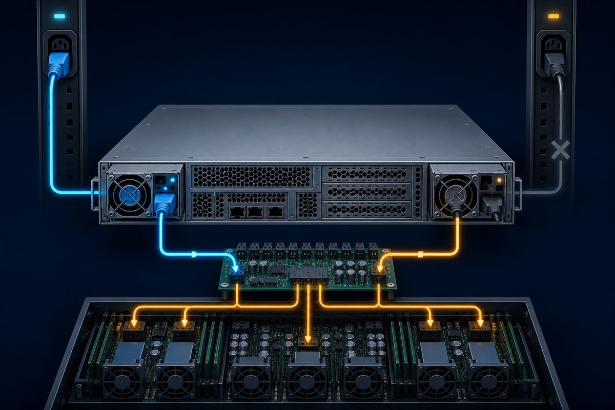
A two-bay rack server often supports 1+1 operation, meaning either module can carry the permitted load. The redundant load limit is therefore based on one module under deployed input and thermal conditions, not the sum of both labels. When both are active, current sharing may place each at a lower load fraction. When one is lost, connector current, heat, noise, and exhaust temperature rise on the survivor.
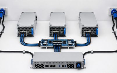
To protect against a rack PDU or branch failure, connect the two modules to appropriately independent A and B feeds. Two cords connected to one PDU still protect against some module and cord faults, but not that shared source. Cable color, labeling, and rack documentation help preserve separation during later maintenance.
Efficiency should be evaluated at the per-module load
80 PLUS certification can provide standardized efficiency evidence for the exact certified model and category. The relevant operating point, however, depends on server load and redundancy strategy. If two active modules share a 600 W DC demand, each operates around a fraction of its individual rating. During a failure, the survivor moves to a different part of its efficiency curve. Model annual input energy across both conditions instead of applying one peak number.
Conversion loss becomes heat inside the rack. Lower loss can ease cooling demand, but acoustic and thermal behavior also depend on fan design, impedance, and firmware. A higher efficiency tier is not a substitute for measurements in the production chassis.
Serviceability is designed before the server reaches the rack
Hot-swap support requires a coordinated module, connector, PDB, and control sequence. The incoming module must limit inrush, the failed path must be isolated, and the shared bus must remain within tolerance. The replacement must be an approved model or a fully qualified equivalent. Physical removability alone does not authorize live service.
A practical service review asks whether the correct bay can be identified, whether the healthy feed remains visible, whether the latch can be reached, and whether insertion can occur without disturbing other cables. The BMC should report loss and restoration of redundancy. Spare strategy should include the exact supported part and revision policy, not merely an advertised wattage.
Rack-level qualification sequence
Include rack density in the acceptance review. Neighboring servers can raise rear-cabinet temperature and increase pressure around exhaust grilles. Measure the candidate in a representative populated rack, with doors and cable-management arms in their normal positions. This reveals recirculation and access constraints that an isolated chassis test cannot reproduce.
- Confirm chassis envelope, PSU depth, connector datum, latch, handle, and extraction clearance.
- Install the server on its production rails and route both power cords to their intended PDUs.
- Exercise minimum and maximum input, cold start, boot, idle, representative workload, and sustained peak.
- Measure bus behavior during fast load changes and fan-speed transitions.
- Record PSU inlet, exhaust, connector, PDB, and critical chassis temperatures.
- Run on each redundant module alone at the maximum permitted load.
- Remove and insert each supported hot-swap module while observing the bus and management state.
- Inspect airflow and service access with the rack door, neighboring equipment, and real cables in place.
This procedure connects module specifications to the deployed rack. It also exposes layout problems that a component bench cannot reproduce.
Choosing among rackmount power approaches
A compact single supply can be appropriate for low-cost systems where planned downtime is acceptable. A 1+1 removable pair supports service continuity when each module can carry the load. Larger multi-module arrangements may support N+1 capacity for higher-power platforms. The choice follows the server’s availability target, rear-panel allocation, workload, facility feeds, and maintenance model.
For a broader discussion of chassis selection and redundancy, see Powernexu’s rack server power supply selection article. The 1U server power supply guide focuses specifically on height, narrow airflow channels, and dense mechanical integration.
Questions that should be resolved before purchase
Can a deeper PSU be used if the rear panel opening matches?
Only if the internal envelope, connector datum, cooling path, guide and latch geometry, PDB, and service clearance all support it. A matching opening does not prove full insertion or electrical compatibility.
Should two rack server PSU ratings be added together?
Only for a supported combined-capacity mode. In 1+1 redundancy, the permitted load must remain within one module’s usable capacity after the other is lost.
Why can a rack server become louder after one PSU fails?
The remaining module carries more load and may increase its fan speed. Chassis airflow can also change when a bay is empty. The exact response is controlled by module and system thermal policy.
Is CRPS size enough to identify a replacement?
No. Depth, connector keying, pinout, rails, signals, management, firmware support, airflow, and derating can differ. Use exact host support information and interface documentation.