A redundant power supply distribution board is the controlled power-path layer between two or more sources and the server’s loads. Its defining work is not simply routing copper: it prevents one source from back-feeding another, coordinates current sharing, preserves the common bus when a module is inserted or fails, and limits downstream faults to the smallest practical branch. A board deserves the word “redundant” only when a specified source or branch fault can occur without taking the protected load outside its allowed voltage and current behavior. Connector fit and assembly scope matter, but the architecture is proven by fault containment.
The board turns independent sources into one survivable bus
Two PSU outputs cannot be treated as ordinary parallel wires. Small differences in output voltage and path resistance can make one module carry much more current than the other. A failed or unpowered source can also become a sink unless its path blocks reverse current. The redundant PDB therefore places a controlled boundary between each source and the common distribution node.
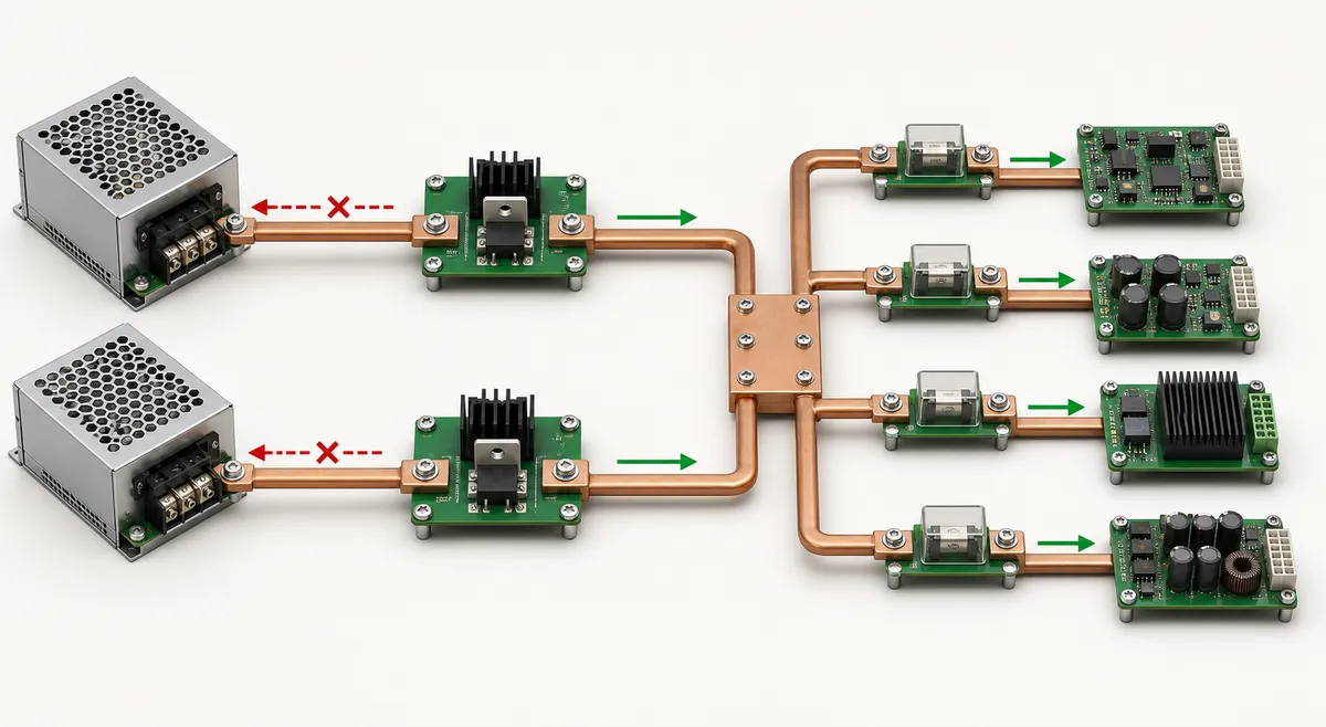
A useful mental model has four layers: source connectors; per-source isolation and hot-swap control; the common bus and energy storage; and protected branches to the motherboard, accelerators, drives, fans, or auxiliary converters. Some server PDBs also generate secondary rails. An official Intel server-board technical specification hosted by Kontron, for example, describes a common redundant PDB that accepts a 1+1 supply arrangement, produces additional 3.3V, 5V, and standby rails, and adds overcurrent protection to 12V rails. That is one documented implementation, not a universal requirement for every PDB.
This power-path focus separates the topic from a CRPS PDB assembly and interface discussion. An assembly article asks what parts belong together and where their interface boundaries lie. Redundant distribution architecture asks what happens electrically when a source, connector, switch, bus segment, or load branch behaves abnormally.
ORing must block the fault, not merely select a source
ORing gives each source a one-way relationship with the common bus. A simple diode can perform that function, but its forward drop creates loss and heat. At server currents, a controller driving a low-resistance MOSFET can emulate an ideal diode with lower conduction loss, subject to device rating, thermal design, layout, and controller behavior.
Texas Instruments’ application report on current sharing in redundant systems explains why redundant sources need the equivalent of output-diode ORing to prevent reverse current during faults and hot swaps. It pairs ORing control with current-share control because these functions solve different problems: ORing protects the bus from an unhealthy path, while sharing determines how healthy modules divide demand.
The critical event is a source-side short. If a module output or connector collapses, the common bus should not discharge into that fault long enough to reset the loads or overstress the blocking device. Reverse-voltage detection, gate turn-off speed, parasitic inductance, MOSFET safe operating area, and local capacitance determine the transient. A schematic that shows two ideal-diode symbols is only the beginning; board layout sets the real commutation loop.
ORing alone does not necessarily impose a load current limit. TI’s documentation for hot-swap and ORing controllers treats source isolation, inrush control, and load-fault protection as related but distinct functions. The TPS2474x datasheet, for example, shows two supplies ORed into one load and explains the separate role of the hot-swap stage during load faults and hot-plug events. A PDB specification should name which function protects each boundary instead of assuming one controller does everything.
Current sharing is a control loop across unequal paths
Healthy modules share only as well as the sources, sense points, control method, and distribution resistance allow. Passive droop sharing intentionally lets output voltage fall slightly as current rises; modules with different currents then move toward a balance. Active sharing uses a share bus or controller to trim module outputs toward a common current target. Both approaches depend on supported source behavior and stable loop interaction.
Equal nameplate ratings do not guarantee equal current. Millivolts of output difference, connector resistance, copper length, temperature, or sense placement can shift the split. That matters because an overloaded module can reach its current limit while total system demand still appears lower than the sum of all ratings. The result may be oscillation, a module dropout, or a sudden transfer to the survivor.
| Function | Primary question | Failure if omitted or misapplied |
|---|---|---|
| Source ORing | Can the bus drive current backward into this path? | One source fault can pull down the common bus |
| Current sharing | How do healthy modules divide sustained demand? | One module may overload before total capacity is reached |
| Hot-swap control | How is insertion current and path turn-on managed? | Bus droop or connector stress during service |
| Branch protection | Which downstream fault is disconnected? | A local short can become a chassis-wide outage |
Remote-sense connections complicate the loop further. Sensing before the ORing device does not compensate its drop; sensing at the common load node can couple modules through the shared bus and must follow the source manufacturer’s supported scheme. The PDB designer should work from documented share and sense behavior, then analyze stability with connector and trace resistance included. An improvised sense connection can make regulation look precise at steady state while destabilizing transitions.
Fault containment continues after the common bus
The common bus is not the end of redundancy. If every load connector is tied to one unprotected copper plane, a shorted cable or converter input can collapse both healthy sources at once. Branch fuses, electronic circuit breakers, hot-swap controllers, or current-limited converters create smaller failure domains. The appropriate device depends on fault energy, normal transients, reset policy, serviceability, and whether the branch must report status.
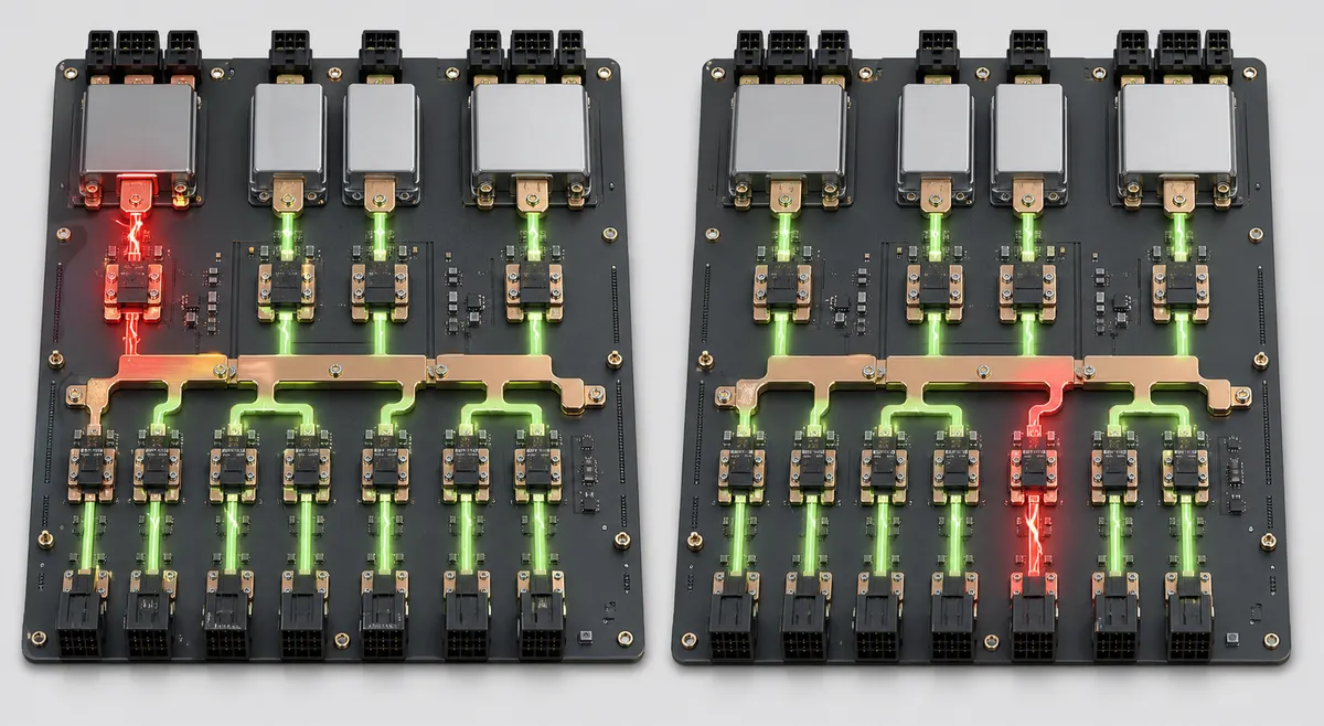
The trip hierarchy must be coordinated. A branch that supplies a capacitive load needs enough startup allowance to avoid nuisance trips, yet it should disconnect before the source modules enter a prolonged current limit that drags down every branch. A fast semiconductor load may need an electronic protection stage; a cable leaving the board may still require a fuse appropriate to conductor protection. No single trip curve is universally correct.
Fault energy also travels through stored capacitance. Bulk capacitors can hold the bus through a brief source transition, but they can deliver substantial current into a downstream short. Placement, series impedance, branch switching, and discharge behavior decide which components experience that energy. The useful design question is not “How much capacitance can fit?” but “Which transition must it bridge, and which fault must it not feed?”
Copper geometry determines electrical and thermal headroom
A distribution board can pass a functional bench test and still have inadequate margin. High-current copper paths develop voltage drop and local heat at neck-downs, vias, connector pins, fasteners, and MOSFET source connections. Current crowds around corners and apertures; parallel planes do not divide perfectly when their geometry or contact resistance differs. Temperature then raises resistance and changes the sharing problem the control loop is trying to correct.
The analysis should follow the worst supported state. With both modules healthy, each source path may carry a fraction of the load. After one source is isolated, its companion input path and the common bus carry the full protected demand. A branch connector may see its maximum even when the aggregate board load is moderate. Board copper, busbars, connectors, switches, sense elements, and fuses all need ratings and thermal evidence under the same ambient, airflow, and duration assumptions.
Airflow deserves architectural treatment because ORing FETs, branch switches, and DC-DC converters may form separate hot spots. The Intel/Kontron example explicitly assigns airflow from PSU fans to PDB converters. Other chassis may use system fans or conduction into a metal carrier. Removing a PSU during service can alter that airflow just as the survivor and its ORing path take more current, making the one-source condition both an electrical and cooling case.
Management should identify the failed boundary
A server that merely reports “power fault” wastes the PDB’s opportunity to localize service. Useful observability distinguishes source present, source output good, ORing path state, share imbalance, common-bus voltage, branch trip, temperature, and restored redundancy where the hardware supports those signals. Telemetry does not replace hardware protection; it shortens diagnosis and prevents a silently degraded system from remaining in service.
The PMBus organization publishes application profiles for server AC-DC power supplies and hot-swap controllers. Those profiles provide a standardized vocabulary where implemented, but a real PDB may combine PMBus, discrete presence and fault pins, GPIO expanders, or proprietary BMC interfaces. The host must know which device owns each alarm and what action follows. A branch trip may call for workload shutdown while a failed redundant source may allow continued operation with an urgent service alert.
The architecture succeeds when faults stay local
A redundant power supply distribution board should be specified as a map of boundaries. For every source path, state how reverse current is blocked, how insertion is controlled, and how healthy modules share. For the common bus, define the allowable transition and stored-energy role. For every major branch, define its conductor capacity, protection behavior, and effect on other loads. Then connect those hardware states to the BMC or service indication that reveals degraded operation.
This method avoids two misleading shortcuts. The first is calling a board redundant because it has two input connectors. The second is assuming a large source capacity protects every downstream path. Real redundancy appears when one defined failure is isolated before it becomes a common-bus failure, while the surviving path remains within its electrical and thermal envelope.
That is also the boundary between this architecture article and Powernexu’s broader server power supply distribution board design overview. The broader page helps frame PDB design responsibilities. Here, the decisive deliverable is narrower and harder: source faults, hot-plug transitions, share errors, and branch shorts must terminate at the intended protection boundary rather than propagate through the chassis.