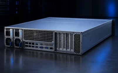
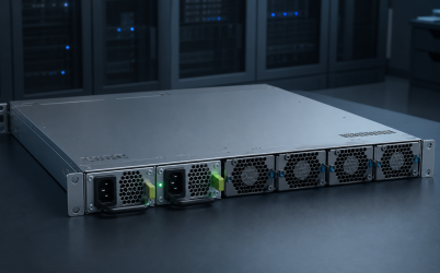
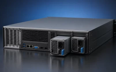
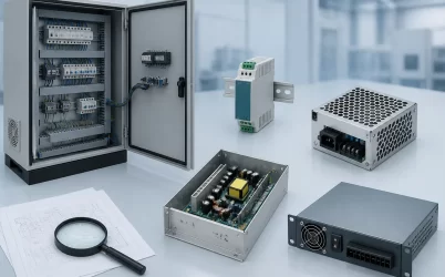
An 800W server PSU CRPS listing identifies a wattage class, not a compatible replacement. Before purchase, match the exact manufacturer part number and revision, CRPS or M-CRPS interface, mechanical envelope, blind-mate connector, pinout, PDB, control signals, PMBus behavior, host approval, input conditions, airflow, and redundancy policy. Also establish whether the seller is offering a bare module, a platform-qualified spare, or a kit. In a 1+1 system, one module’s usable output normally must carry the permitted server load after its partner becomes unavailable; two 800 W labels do not establish 1,600 W of protected capacity.
Quick answer: use 800W as a search filter, not a replacement key
An 800W CRPS candidate is suitable only when its capacity and every host-facing interface match the intended server. Start with the supported platform part number when replacing an existing PSU. For a new integration, obtain the module datasheet, mechanical drawing, connector and pinout definition, PDB documentation, management requirements, input and environmental limits, and evidence for the intended redundant operating mode. Do not infer compatibility from wattage, CRPS terminology, connector appearance, Platinum wording, or a seller’s claim that the unit is “server compatible.”
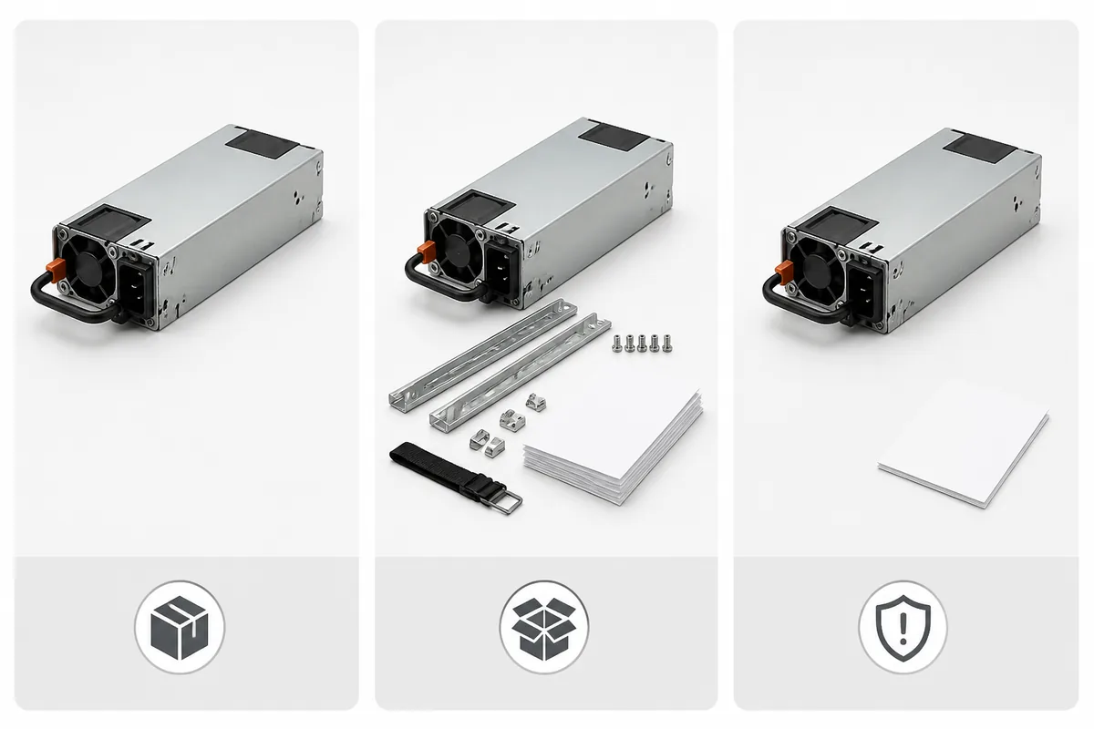
Commercial results for “800W server PSU CRPS” can place materially different deliverables beside one another. Their wattage may be similar, but the buyer’s integration responsibility is not.
| Listing context | What may be included | Best evidence | Primary purchasing risk |
|---|---|---|---|
| Platform-qualified replacement or kit | A module approved for named server platforms, potentially with platform-specific hardware or documentation | Platform support matrix, option or spare number, and complete kit contents | Buying the correct wattage but the wrong platform generation, option number, or kit |
| Standalone CRPS or M-CRPS module | The power module without a server-specific cage, PDB, harness, firmware integration, or host approval | Exact module datasheet, mechanical drawing, interface definition, and revision | Treating an integration component as a drop-in field replacement |
| Compatible or alternate replacement | A third-party or cross-referenced unit claimed to replace another part | Written cross-reference, host qualification evidence, exact revision control, and warranty scope | Relying on a catalog title without proof of electrical and behavioral equivalence |
A platform-qualified kit and a standalone module represent different purchasing boundaries. The kit may include platform-specific parts and host support, while the standalone module normally leaves integration to the buyer. Neither category establishes compatibility with hardware from the other.
CRPS and M-CRPS should also remain distinct in the comparison record. Each candidate must be identified by its applicable interface family or specification, exact model, revision, supported PDB, and host evidence rather than being reduced to the generic phrase “common redundant PSU.”
Gate 1: prove that 800W covers the degraded operating state
The relevant capacity question is not whether the server usually draws less than 800 W. It is whether one candidate module can support the highest permitted server demand while the redundant partner is failed, disconnected, or being replaced. A useful first condition is:
Usable output of one module under deployed conditions ≥ highest permitted server demand during one-module operation.
“Usable output” must come from the exact module documentation. The nameplate value may be conditional on the AC input, ambient temperature, altitude, airflow, output distribution, or other model-specific limits. Average workload measurements also do not establish transient suitability. Processor boost behavior, accelerator activity, drive spin-up, fan response, and simultaneous component loading can briefly demand more than a long-duration average suggests.
Define at least four states before requesting a quotation: normal operation with both modules available, operation after one module or feed is lost, startup of the maximum supported configuration, and the service interval while a replacement is inserted. If a power cap is required to remain within one-module capacity, record who configures it, whether it persists across firmware changes, and how the system behaves if that control is absent.
The broader server PSU wattage methodology explains how to build a configuration-level capacity envelope. For this 800 W purchase, the practical output should be a documented maximum server configuration and a single-module operating limit, not merely a statement that “800 W should be enough.”
Gate 2: match the bay, PDB, and host protocol as one interface
The module must occupy the same mechanical contract
Obtain dimensioned drawings for the candidate and the supported bay. Compare the complete envelope, insertion depth, front and rear features, keying, latch position, handle clearance, guide rails, connector location, and extraction path. Similar-looking narrow modules can differ at precisely the features that control insertion or blind mating.
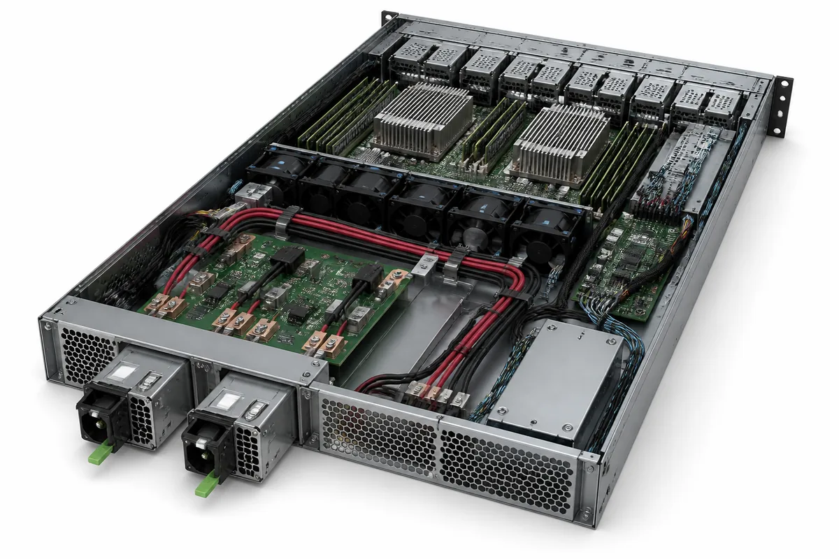
Airflow direction and pressure requirements belong in the same comparison. A module that physically enters the bay may still be unsuitable if its fan direction conflicts with the chassis airflow or if the installed resistance prevents it from meeting the documented thermal operating condition. Do not substitute catalog photographs for mechanical drawings.
The PDB determines where mechanical fit becomes electrical fit
The blind-mate interface connects more than the main output bus. Depending on the exact design, it may also carry standby power, enable and status functions, presence detection, remote sense, current-sharing connections, and management communication. The same connector shell does not establish that these contacts have the same assignments, sequence, rating, or behavior.
Compare the candidate pinout line by line against the PDB and host interface documentation. Then confirm the PDB’s supported module list, current paths, output harness, downstream connectors, and fault-isolation method. Powernexu’s CRPS PDB interface guide maps the boundaries among the module, blind-mate connector, board, wiring, control signals, and server load.
PMBus support is not a complete management specification
A listing that mentions PMBus does not establish compatibility with the server’s BMC. The host may expect particular identification data, status words, telemetry fields, alert behavior, timing, addressing, firmware responses, or fault records. Some platforms may flag an unsupported PSU even when the main DC output is present; the precise response is platform-specific.
Request the supported command and telemetry documentation where available, along with any host firmware prerequisites. For a replacement purchase, the platform support list and exact approved spare number are generally stronger evidence than a generic statement that both modules use the same management protocol.
Use an evidence-based worksheet to compare exact candidates
A comparison worksheet prevents a supplier’s strongest marketing field—usually wattage or efficiency—from obscuring missing compatibility evidence. Each row should identify the required condition, the supplier’s evidence, any exception, and the person accepting that exception.
| Compatibility gate | Evidence to request | Pause or reject when |
|---|---|---|
| Product identity | Manufacturer, exact part number, revision, date or lot traceability, and condition | The quotation substitutes a family name or photograph for an exact part number |
| Host status | Named server models, supported configurations, option or spare number, and firmware conditions | Compatibility is claimed only from wattage or connector appearance |
| Capacity | Output limits under the deployed input, temperature, altitude, and airflow conditions | The full 800 W rating is assumed without its operating conditions |
| Mechanical fit | Controlled drawing and supported bay or cage information | Dimensions, keying, latch, connector position, or airflow direction remain unknown |
| Electrical interface | Connector specification, verified pinout, output and standby definitions, signal timing, and ratings | The pinout is unavailable or inferred from another model |
| PDB integration | Supported PDB part number, harness scope, current path, and module combination rules | The seller cannot identify the board or assembly used with the module |
| Management | PMBus or other management documentation, BMC support, telemetry, alerts, and firmware notes | “PMBus compatible” is the only management evidence |
| Redundant behavior | Supported 1+1 or other topology, load-sharing behavior, fault isolation, and hot-replacement documentation | Two units are described as redundant without host-level evidence |
| Commercial scope | Included module, cage, PDB, cables, cord, blanking hardware, documentation, warranty, and return terms | The quotation does not distinguish a bare module from an installable kit |
This worksheet can be attached to a broader set of testable server power supply requirements when the module is being qualified for a new platform rather than purchased as an approved spare.
For a field replacement, begin with the server manufacturer’s service documentation, supported option list, or spare-parts record. This identifies the platform-level item the server vendor supports. An exact approved spare normally carries more compatibility weight than a standalone module with similar headline specifications.
For a new design or alternate-source project, move next to the module manufacturer’s controlled documentation. The LITEON 800W server power supply datasheet is an example of the model-level evidence needed to compare electrical, mechanical, signaling, and operating requirements. It demonstrates the required documentation type; it does not establish fit in a particular server or interchangeability with another 800W module.
Distributor and marketplace pages are useful for availability, price, lead time, and condition, but they should not override controlled drawings, datasheets, or platform support records. If a listing shortens the part number, omits a revision, combines several models under one page, or uses a representative image, obtain written clarification before placing the order.
An efficiency tier describes conversion performance under the applicable certification program and test conditions for the exact certified model. It does not prove bay fit, pinout compatibility, BMC recognition, surviving-module capacity, or host support. Request evidence tied to the quoted part number and revision rather than transferring an efficiency claim across an entire product family.
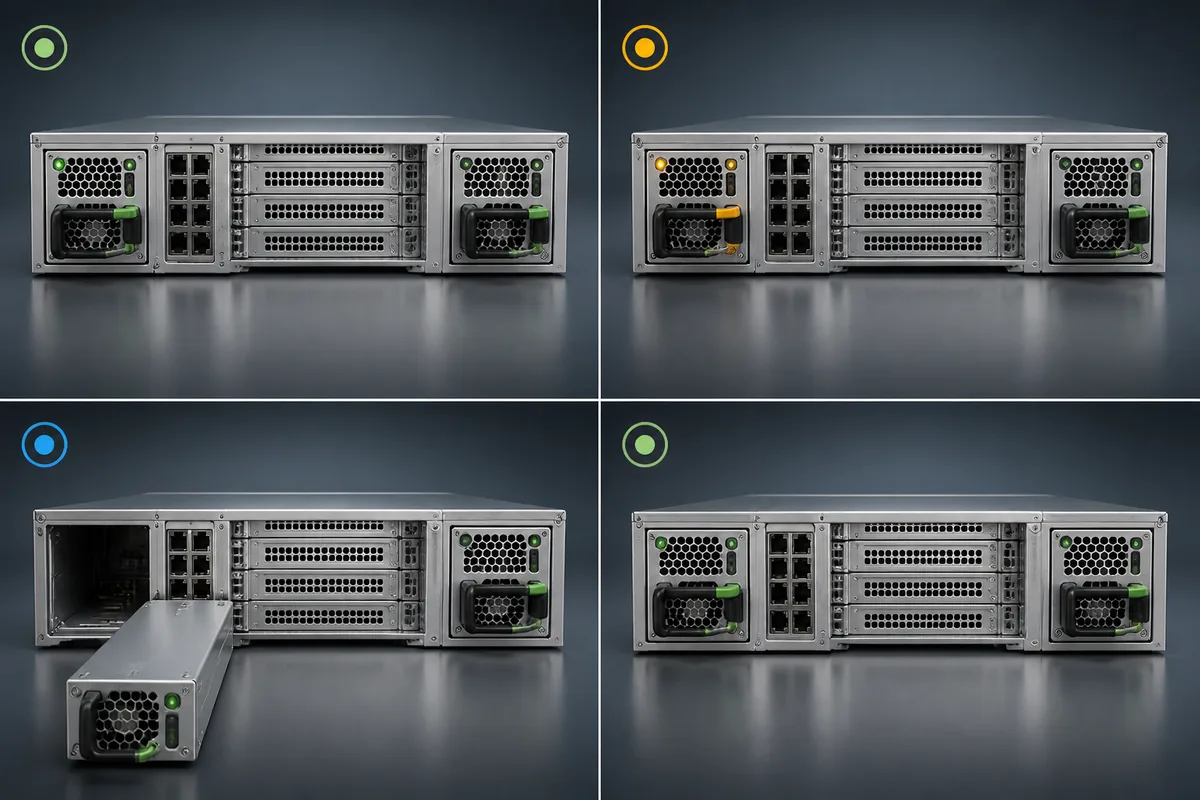
Hot-plug describes a supported live insertion and removal capability, not merely a removable handle. The platform must maintain the shared bus through removal, isolate the departing unit, control insertion behavior, recognize the replacement, and restore the intended redundant state. Evidence must cover the module, connector sequencing, PDB, host controls, firmware, and service procedure as an assembled system.
Redundant likewise describes system behavior after a defined failure. Two installed modules may protect against module loss, but they do not automatically protect against a shared PDB fault, common AC branch, common cord path, firmware defect, or cooling failure. If independent A/B feeds are required, the quotation and validation plan should identify each complete path from module inlet to upstream rack power source.
Turn the selected part into a repeatable spare
Compatibility evidence should be followed by controlled host testing when a module is being integrated or approved as an alternate. Do not conduct live-removal testing in production equipment unless the platform documentation permits it and trained personnel follow the required safety and service procedure.
- Verify received identity: compare the manufacturer, full part number, revision, condition, and supplied kit contents with the purchase order.
- Inspect fit without forcing insertion: confirm rails, keying, latch engagement, connector alignment, extraction clearance, and airflow direction.
- Observe normal paired operation: check host recognition, PSU status, available telemetry, alarms, and current sharing. Current need not be exactly equal unless the applicable specification requires a defined tolerance.
- Exercise the permitted degraded state: under a controlled representative load, confirm that loss of the selected module or feed does not exceed the surviving unit’s supported envelope.
- Evaluate replacement and recovery: verify the documented removal and insertion sequence, fault isolation, alarm transitions, recognition of the replacement, and restoration of the protected redundant state.
- Check thermal behavior: operate under the intended chassis airflow and environmental conditions rather than relying on an open-bench result.
A successful test applies to the recorded combination of module revision, PDB, chassis, BMC or system firmware, input source, airflow configuration, and server load. A later change to any of these elements may require review rather than automatic extension of the original approval.
Make the purchase order preserve the compatibility identity
The final order should name more than “800W CRPS PSU.” Record the manufacturer, exact part number and acceptable revision, supported host and PDB, required condition, included hardware, documentation, warranty, approved alternates, and whether substitutions require written authorization. For kits, list every expected component. For bare modules, state that the cage, PDB, harness, or cords are excluded rather than leaving their status ambiguous.
Carry the same identity into spare inventory. A shelf label or asset record should connect the module to its approved server platforms, PDB, firmware baseline, and qualification record. This prevents a physically similar 800 W unit from being treated as an equivalent spare years after the original purchase.
The useful outcome of an 800W server PSU CRPS search is therefore not the first product with the right wattage. It is an exact, traceable module or platform kit whose capacity, interfaces, host behavior, redundant operation, and quotation scope are supported by evidence. Once those fields are closed, 800 W becomes a meaningful part of the specification instead of a risky shortcut for compatibility.