An 800W dual redundant server power supply should be approved as a 1+1 operating configuration, not assumed to provide 1,600W of protected output. The 800W figure may describe each removable module, while the meaningful resilience figure is the output that one surviving module can deliver under the actual input voltage, inlet temperature, airflow, and server load. The purchase also needs to identify whether it includes one spare module, a matched pair, or the complete cage, power distribution board (PDB), harnesses, and host-specific hardware. These distinctions determine whether the system will continue operating after a module failure and whether the quoted equipment can actually be installed.
Quick answer: qualify an 800W dual redundant server power supply from the failed state outward. Establish the supported output of one surviving module, then confirm that the chassis, cage, blind-mate connector, PDB, cables, control signals, firmware, cooling path, and upstream feeds support the same 1+1 configuration. Finally, make the quotation state its exact scope. Two 800W labels describe installed hardware; they do not, by themselves, define protected capacity, feed redundancy, or a deployable server assembly.
The number that matters appears when one module disappears
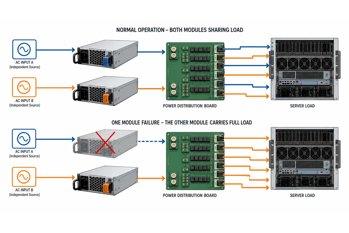
A dual redundant arrangement passes through several electrical states during normal service and maintenance. In a typical 1+1 design, both modules may share the server load during normal operation, but either module may need to carry the protected load alone after its partner fails or is removed. The surviving-state rating therefore controls the server configuration that can remain online with redundancy degraded.
| Operating state | What changes | Evidence required |
|---|---|---|
| Both modules available | Load sharing, monitoring, and cooling operate in the normal configuration. | Supported pair, current-sharing behavior, total server load, and normal alarms. |
| One module unavailable | One conversion path carries the protected server load. | Single-module output under the deployed input and environmental condition, plus PDB and harness limits. |
| Live replacement | The bus and control system experience removal and insertion while the server remains powered. | Host-approved hot-plug procedure, insertion behavior, inrush control, and restored redundancy indication. |
| One upstream feed lost | One or more modules may lose input even though the modules themselves are healthy. | Input-feed topology, PDU allocation, cord arrangement, and the server response to feed loss. |
| Recovery after replacement | The new module joins the pair and management status changes from degraded to redundant. | Pairing policy, firmware behavior, current sharing, and BMC or PSU telemetry. |
Consider a hypothetical server with a credible worst-case demand of 620W. If one module is documented to deliver 800W in the actual operating condition, the simple output difference is 180W. That difference is not automatically usable headroom: connector current, PDB branches, transient response, fan power, startup behavior, and workload excursions may impose tighter limits. If the hypothetical degraded rating fell to 700W at a different environmental condition, the same server would have only 80W of gross margin. The example shows why the correct comparison is surviving output versus permitted server demand, rather than 800W multiplied by two.
The calculation also needs a defined load boundary. A CPU-only estimate may omit accelerators, storage spin-up, memory expansion, fan response, or PCIe devices. Conversely, an instantaneous laboratory peak may not represent a permitted server operating state. The requirement should name the workload and configuration that the host is allowed to run while one module is unavailable. If the platform documentation imposes a reduced-performance or power-capping policy in degraded operation, that policy belongs in the 800W decision rather than being treated as an operational surprise.
An 800W listing can describe three different purchase scopes
Commercial confusion often begins with the noun attached to the wattage. A supplier may quote a single removable module, two modules sold as a matched pair, or a complete redundant assembly. All three can be described with 800W language, but they solve different purchasing problems.
| Quoted scope | What it may contain | When it is normally relevant |
|---|---|---|
| One module | One removable converter with its own label and part identity. | Maintaining a qualified server fleet or replacing one failed module. |
| Matched pair | Two modules identified for operation together, sometimes with pairing or revision conditions. | Populating an existing compatible cage when the PDB and host are already defined. |
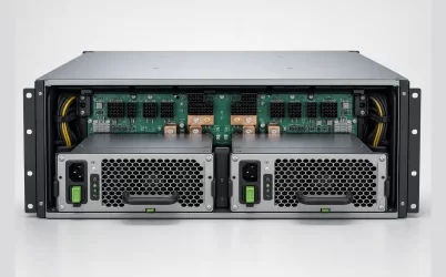
| Complete assembly | Modules plus cage, PDB, harnesses, controls, and possibly cords or mounting hardware. | New server integration or a retrofit where the host-side power architecture is not already installed. |
An official manufacturer product page can describe an 800W+800W redundant product as a pair, which illustrates why a marketplace title should not be treated as a bill of materials. The SilverStone Gemini 800-2U Gold listing is useful evidence of that naming distinction, but it does not establish compatibility with an unrelated server, cage, PDB, or firmware baseline.
For a replacement order, one module may be the correct scope if the installed assembly is already qualified and the supplier identifies the exact replacement identity. For a new build, buying two loose modules without the mating cage and PDB can leave the integrator responsible for interfaces that were never included in the quotation. The commercial question is therefore not simply how many units are present. It is which parts create the tested power path and which parts remain the customer’s responsibility.
The host, not the marketplace title, defines the interface
The phrase dual redundant does not identify a universal mechanical or electrical standard. Listings commonly divide between 1U and 2U systems, CRPS-style modules and proprietary assemblies, and module-only products and complete kits. A module that occupies a similar bay can still fail to mate with the host because the connector datum, latch, keying, insertion depth, airflow direction, or PDB interface differs.
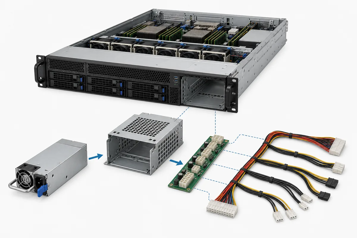
Begin with the server configuration and trace toward the module. The relevant chain usually includes the chassis bay, cage or guide system, module envelope, blind-mate connector, PDB, output harnesses, motherboard and accelerator connectors, standby supply, control signals, communication bus, and firmware policy. The 800W rating answers only one part of that chain. The wider complete 2U assembly qualification problem remains relevant when the target platform uses a 2U cage, but the present question is narrower: whether the specific dual-800W arrangement remains protected after one source is lost.
The PDB deserves special attention because it can determine whether two modules become two usable sources or merely two converters connected to a shared and insufficiently documented interface. It may carry the common output bus, isolation or ORing devices, current-sharing signals, standby power, management communication, and multiple downstream branches. A module can be electrically capable while the PDB connector, copper path, branch protection, or control implementation is not rated for the intended assembly. Powernexu’s article on the CRPS PDB fault boundary provides the broader architecture context; for an 800W pair, the practical task is to identify which PDB revision is part of the approved configuration.
Do not infer signal compatibility from a common connector shell. PS_ON, PGOOD, current-share contacts, presence detection, fan or thermal signals, and PMBus or other management lines may be arranged differently between platforms. The exact pin assignment may not need to be published for a standard replacement, but the supplier and host documentation must still establish that the module is supported in that mating assembly. An undefined signal path is an unresolved compatibility condition, not evidence of interchangeability.
Two modules are redundant only across the intended failure boundary
Module redundancy and input-feed redundancy are related but separate claims. If two modules are connected to separate rack PDUs or branch circuits, a single upstream feed failure may leave the other module energized. If both input cords terminate at the same upstream PDU, breaker, maintenance bypass, or facility source, the pair may still protect against one module failure while sharing a larger common failure point.
The input arrangement should therefore be written as part of the system configuration. Name which module connects to which source, whether the sources are genuinely independent for the failure being considered, and whether the server remains within its permitted load after one source is lost. A second cord routed through the same upstream device can improve connector or branch capacity without creating the same failure-domain separation as an A/B arrangement.
The common DC side has its own boundary. A PDB, backplane, standby circuit, management bus, or downstream branch may remain shared even when the AC inputs are separated. A short or control fault in one region should be examined for its effect on the common bus and the healthy module. The purpose is not to claim that every 800W pair has a particular isolation design; it is to make the supplier identify the supported fault behavior of the exact assembly.
Management behavior also affects operations. A server may continue running with one module absent while reporting degraded redundancy, or it may impose a power policy, alarm, or service restriction. The BMC display should not be treated as proof of capacity. It is useful when it reports module presence, input state, output condition, and redundancy status, but those signals must correspond to the documented electrical behavior. A green status after installation does not prove that a high-load degraded state is supported.
Nominal 800W output has an operating envelope
The module rating has meaning only under its documented conditions. Input voltage and frequency, inlet temperature, airflow direction and volume, altitude, rack orientation, load distribution, and neighboring heat sources can influence the available output or the protection response. A module qualified on an open bench may not have the same thermal margin inside a densely populated server bay with a restrictive grille, contaminated filter, or changed fan curve.
Airflow is particularly important after one module is removed. The remaining module may carry more electrical load and produce more heat, while the empty bay or service condition changes pressure balance. The host may also increase fan speed, which raises server consumption and acoustic output. Those effects belong in the degraded operating model. A statement such as one module supports 800W is incomplete unless the condition, cooling arrangement, and any derating are identified.
Distribution losses deserve similar treatment. The module output is not the same measurement point as the processor, GPU, storage, or motherboard connector. PDB copper, mating contacts, harnesses, overcurrent protection, and local connectors each carry part of the load. A dual-800W configuration should therefore identify the most constrained branch, not just the source rating. This matters in servers with many storage devices or accelerators, where a total server wattage can conceal a concentrated current demand at one connector zone.
Ask the supplier for the documents that establish the operating envelope: output rating conditions, derating information where applicable, airflow requirement or direction, protection behavior, input range, mechanical drawing, interface definition, and host or assembly support statement. Exact values should come from the model revision being quoted. If the supplier cannot connect the 800W claim to the intended chassis and degraded state, the unresolved condition should remain visible in the purchase review.
Write the RFQ so 800W has one meaning
Separate capacity, compatibility, failure scope, and supplied hardware in the RFQ. Require the exact manufacturer part number and revision, and identify whether each line item is one module, a pair, or the complete cage/PDB/harness assembly.
- Protected capacity: Documented output with one module unavailable at the specified AC input, inlet temperature, airflow, altitude, workload, and host power policy.
- Host interface: Approved server or chassis, cage, blind-mate interface, PDB, harnesses, branch connectors, controls, management, firmware, and airflow direction.
- Failure boundary: Required 1+1 behavior, feed arrangement, tolerated module and feed events, isolation or sharing evidence, and degraded/restored indications.
- Commercial scope: Module quantity, revisions, included hardware, documents, and approved substitutions.
For replacements, attach module-label records, PDB and cage identity, server configuration, firmware baseline, and the authorized service procedure. For new integration, request an assembly drawing and explicit exclusions.
At receiving, verify identity, revision, quantity, keying, airflow, included hardware, documentation, and condition. Under an authorized procedure, confirm host recognition, expected redundancy status, and supported operation with one specified module or feed unavailable. Approve only when the record names the surviving capacity, qualified assembly, covered failure boundary, and supplied hardware.