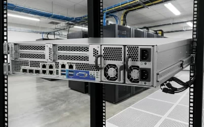
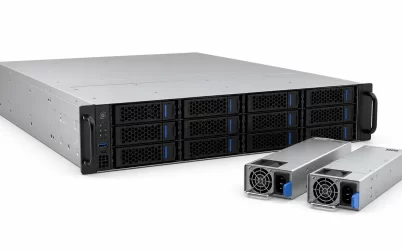
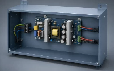
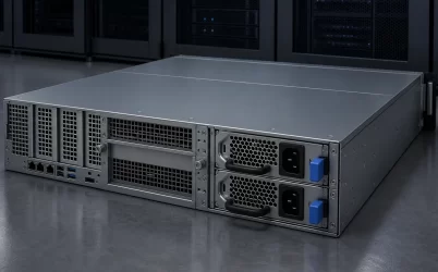
Server power supply voltages do not describe one standard number. They describe several electrical domains along the path from the facility source to the processor: nominal rack AC, the PSU’s accepted input envelope, a regulated DC output or distribution bus, and the lower-voltage rails created near CPUs, GPUs, memory, and other loads. References to 120V, 208V, 240V, 12V, 48V, and 800V therefore answer different questions. Before using any voltage for selection or design, attach it to a physical measurement point, identify whether it is AC or DC, and determine which assembly converts or regulates it.
Quick answer: every voltage needs electrical coordinates
A server does not have one universal operating voltage. The rack may provide nominal 120V, 208V, 230V, or 240V AC, but the exact PSU must document an input range that includes the deployed source. The PSU or rack power system then converts that input into a distribution voltage, commonly 12V in many conventional servers or 48V in some higher-power architectures. Point-of-load converters create lower rails for semiconductor loads. Emerging 800V DC designs represent another system-level architecture; they do not imply that an ordinary server PSU accepts 800V DC.
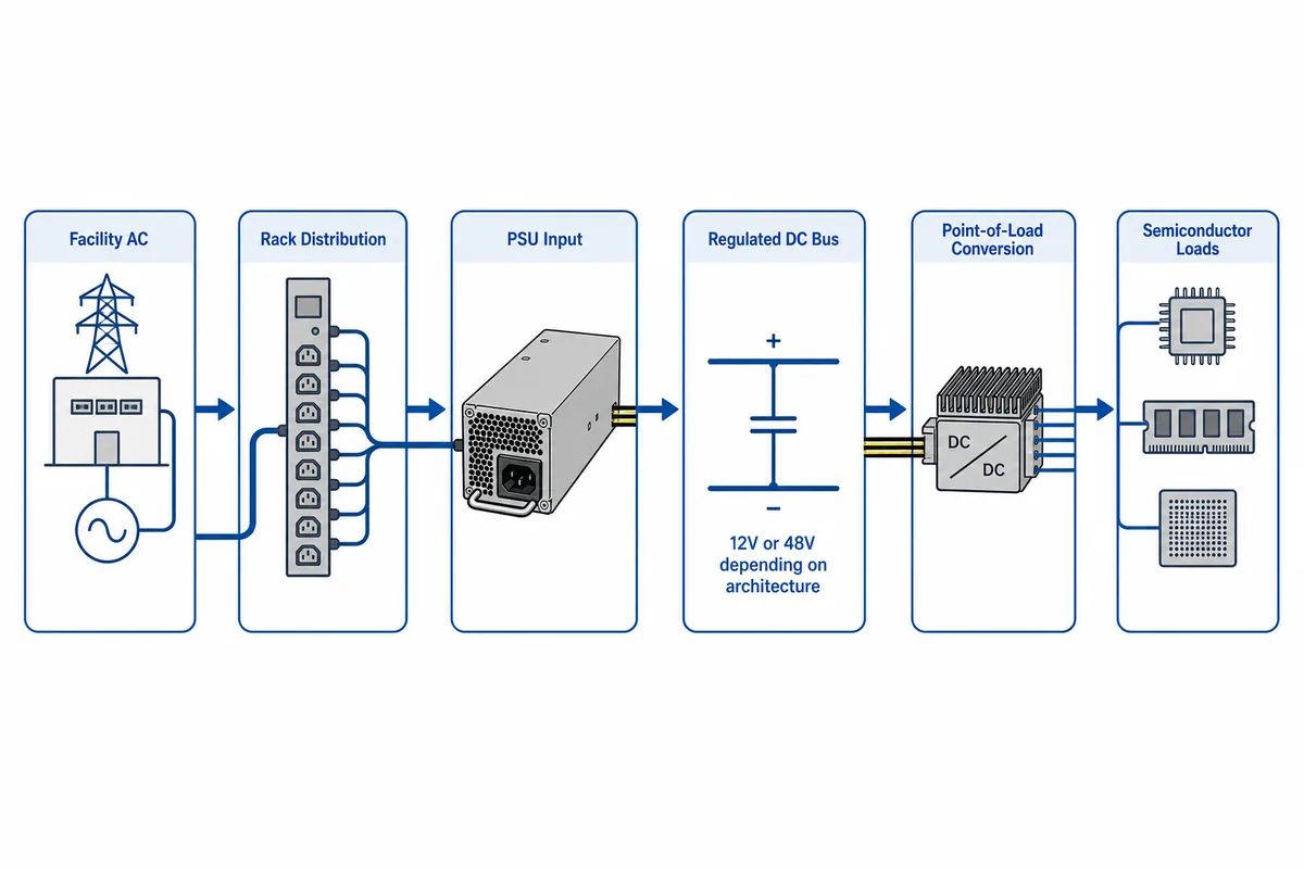
The power flow crosses several voltage domains; delivered real power is slightly lower after each conversion because converters and conductors have losses. Trace it in this order:
- Facility and rack: nominal AC reaches the outlet through switchgear, UPS equipment, branch circuits, and the rack PDU.
- PSU input: the exact module accepts only its documented voltage, frequency, and operating envelope.
- Conversion and distribution: the PSU or rack shelf creates a regulated bus, commonly 12V or, in some architectures, 48V.
- Point of load: board regulators create the lower rails used by processors, memory, and accelerators.
| Reference | Boundary to identify | What it does not prove |
|---|---|---|
| 110/120V AC | Source, outlet, and PSU inlet | Exact accepted range or full output |
| 208/220/230/240V AC | Source, outlet, and PSU inlet | Interchangeability or universal acceptance |
| 12V DC | PSU output, PDB bus, branch, or DC input | Pinout, capacity, or compatibility |
| 48V DC | Rack or server distribution bus | Acceptance by equipment designed for 12V |
| 800V DC | Dedicated upstream or intermediate architecture | Direct acceptance by a conventional server PSU |
Conversion may move from an individual PSU to a rack shelf or dedicated high-voltage stage. In every case, record the physical boundary, AC or DC designation, power-flow direction, owning assembly, and controlling document.
AC labels describe the source, not the internal server bus
Numbers such as 120V, 208V, 230V, and 240V usually refer to nominal upstream AC conditions. They are not substitutes for the accepted input range printed in the exact PSU documentation. A nominal 208V rack source, for example, must still fall within the module’s stated limits after applicable source variation is considered. The correct frequency, inlet, cord, outlet, branch protection, and host configuration must also agree with that deployment.
The labels arise from different distribution contexts. In North American facilities, 208V is often obtained line-to-line from a 120/208V three-phase wye system, while 120V is available line-to-neutral. Other installations commonly use nominal 230V or 240V arrangements. These descriptions help identify infrastructure, but they do not establish the complete input behavior of a particular server PSU.
Input voltage can also affect current and available output. For an approximate single-phase input calculation:
AC input current ≈ DC output power ÷ (AC voltage × efficiency × power factor)
This relationship explains why a lower input voltage generally requires more input current for the same DC output. It is not a replacement for the PSU nameplate or platform documentation because efficiency, power factor, output derating, and workload all vary with operating conditions. Some modules support a broad input envelope but provide reduced output under part of it; others are intended only for a documented high-line range.
Readers making a rack-source decision can use the more focused server PSU input-voltage matching workflow. The distinction here is that AC input is only the first voltage domain in the server power path.
Why 12V and 48V describe different distribution choices
Many conventional server power assemblies convert AC into a principal 12V DC output. A PDB may combine redundant modules, isolate faults, and distribute that bus to the motherboard, storage, fans, or accelerator branches. Local DC-DC converters then produce the lower rails used by individual electronic loads. This is a common architecture, not a universal pinout or output specification.
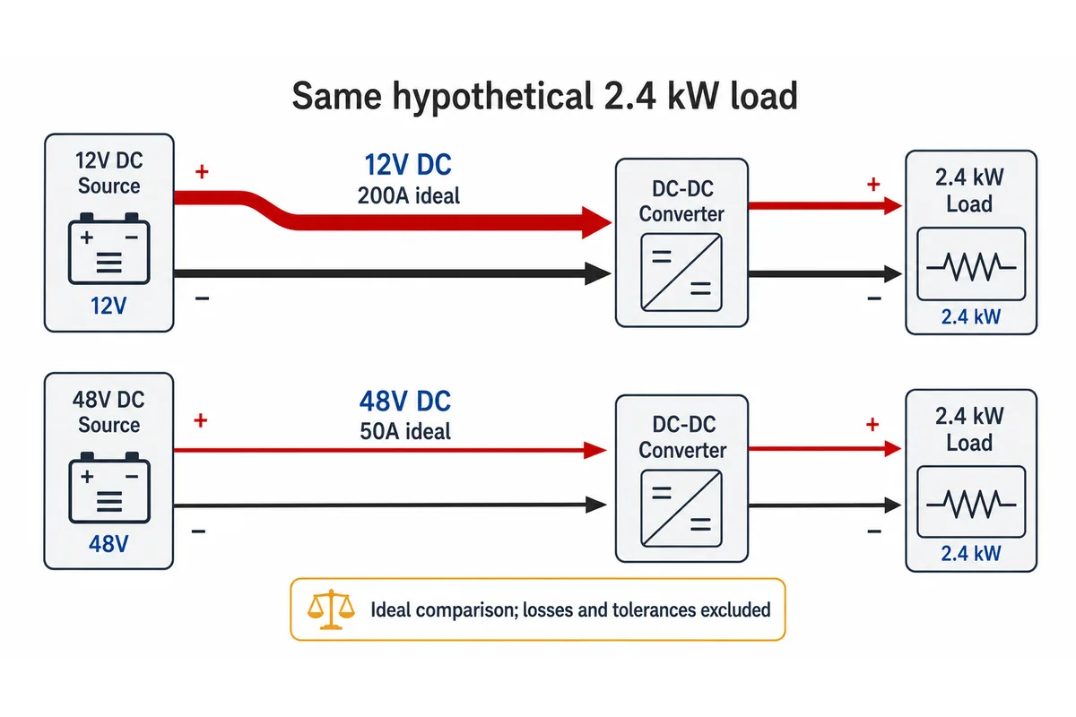
A 48V architecture distributes the same power at a higher voltage and lower current before converting it closer to the load. The attraction becomes clear from the basic relationship P = V × I. In a hypothetical ideal 2.4kW distribution path:
- At 12V, the bus current would be 200A.
- At 48V, the bus current would be 50A.
The example ignores conversion losses and voltage tolerance, so it is not a product-sizing result. It demonstrates why raising the distribution voltage can reduce current through busbars, connectors, and board conductors. If conductor resistance remained equal, resistive loss would scale with the square of current; actual systems also change conductor geometry, connector design, conversion placement, and protection strategy.
The trade-off is an added conversion boundary. A 48V bus normally requires downstream conversion before it can supply loads designed around 12V or lower rails. That conversion consumes space, produces heat, and needs coordinated startup, fault handling, and telemetry. A 48V label therefore describes an architectural choice rather than a drop-in upgrade for a 12V module.
Even “12V output” is incomplete without coordinates. It could refer to the main output of an AC-DC module, the combined bus after a redundant PDB, one branch connector, or the input to a motherboard regulator. If the term appears in a product listing, the cautions in Powernexu’s 12V DC redundant server PSU boundary analysis help separate output-bus information from replacement claims.
Where 800V DC fits—and where it does not
Growing AI and HPC rack power has renewed interest in distributing power at substantially higher DC voltage. At a fixed power level, higher voltage reduces current, which can reduce the amount of copper and the conduction loss associated with a given resistance. An 800V DC architecture may place centralized AC-DC conversion upstream and distribute high-voltage DC toward dedicated rack or server conversion stages.
This is a system architecture, not a new universal input rating for conventional hot-plug server modules. Texas Instruments’ technical discussion of 800V DC data-center architecture presents the voltage as part of a wider conversion chain for high-power computing. The engineering implication is that 800V belongs on an architecture diagram only where equipment is specifically designed for that domain.
Higher-voltage DC also changes the implementation problem. Isolation, creepage and clearance, connector construction, precharge, fault interruption, personnel protection, service procedures, and conversion-stage placement all require deliberate design. DC interruption deserves particular attention because a DC circuit does not provide the periodic current zero crossing available in AC systems. Appropriate switching and protection hardware must therefore be selected for the actual DC voltage and prospective fault conditions.
An architecture document mentioning 800V DC does not authorize connection of that bus to an AC-input CRPS module, a 48V server input, or a 12V PDB. Dedicated conversion equipment must create the voltage expected at the next boundary. Until the exact hardware and interface documentation say otherwise, 800V DC should be treated as an upstream or intermediate domain—not as a direct server PSU substitute.
Each converter changes ownership of regulation and protection
A useful voltage map shows not only the value but also which assembly owns it. The facility electrical system owns the nominal source. The PSU manufacturer defines the accepted module input and regulated output. A PDB may combine and route power without changing the nominal voltage, although some distribution assemblies also contain auxiliary converters. Motherboard and accelerator regulators own their local rails and dynamic response.
Protection follows the same boundaries. Upstream branch protection does not replace PSU input protection, and PSU output protection does not necessarily protect every downstream connector or board trace. A PDB may add branch fuses, electronic protection, ORing devices, current sensing, or standby conversion, but those functions are implementation-specific. The voltage number alone does not reveal where a short circuit will be isolated.
Physical interfaces are equally important because every domain crosses a connector, busbar, card edge, or soldered connection. The interface must support the documented voltage, current, polarity, sequencing, temperature rise, and fault behavior. Power contacts can share a housing with standby power, present signals, enable controls, current-share lines, and management communications. Those signal levels must come from the exact interface documentation; they cannot be inferred from the main bus voltage.
Redundancy adds another ownership question. Two supplies may feed a common 12V or 48V bus, but the PDB and host policy determine how they share current, block reverse energy, and respond when one module disappears. Equal nominal output voltage is necessary for many shared-bus designs, but it does not by itself establish that two modules can operate together.
Decode a voltage claim with a boundary worksheet
A compact worksheet prevents nominal source voltages, accepted input ranges, distribution buses, and component rails from being copied into the same specification column. Create one record for every voltage that appears in a datasheet, drawing, marketplace listing, rack schedule, or architecture paper.
| Field | Question to answer | Why it changes the interpretation |
|---|---|---|
| Value and notation | Is the figure nominal, minimum, maximum, a range, or a tolerance band? | A nominal 208V source and an accepted PSU input range are different specifications. |
| AC or DC | What waveform and frequency apply, or what DC polarity applies? | The same numerical value cannot be transferred between AC and DC equipment. |
| Physical point | At which outlet, inlet, connector, busbar, PDB node, or load terminal is it defined? | The measurement point identifies the actual voltage domain. |
| Power-flow direction | Is the value an input, output, intermediate bus, standby rail, or control signal? | Input acceptance and output delivery authorize different decisions. |
| Owning assembly | Which PSU, shelf, PDB, motherboard, accelerator, or regulator creates or controls it? | The responsible assembly supplies the applicable limits and protection behavior. |
| Operating condition | What load, input, temperature, airflow, redundancy state, and startup condition apply? | Available output and tolerance can change across the operating envelope. |
| Evidence | Which exact model document, revision, drawing, or platform manual supports the value? | A general architecture source cannot establish model-specific compatibility. |
| Authorized decision | Does the evidence support facility planning, energization, capacity analysis, interface design, or component replacement? | A fact valid for one purpose may be insufficient for another. |
Consider four statements that might appear in one server project. “The rack provides nominal 208V AC” describes the available source. “The PSU input envelope includes that source condition” establishes basic input acceptance, subject to the rest of the documented conditions. “The PSU assembly produces a 12V main bus” identifies an internal output domain. “The motherboard creates processor rails from that bus” identifies another conversion stage. None of the four statements can replace the others.
The same discipline prevents three frequent category errors: using a facility nominal voltage as though it were an exact PSU range, using a DC output voltage as though it were a replacement part number, and treating an emerging architecture voltage as though installed equipment already supports it. Each error disappears when the value is attached to its boundary, direction, owner, and evidence.
A complete voltage map permits the right decision at each boundary
Read server power supply voltages as a connected sequence, not a list. Nominal AC guides facility and rack planning. The exact PSU input envelope determines whether a module can be energized and which output conditions apply. A 12V or 48V bus describes power distribution within a particular platform. Point-of-load rails belong to downstream regulators; 800V DC belongs only to architectures designed for that high-voltage domain.
When every voltage has a measurement point and owning assembly, the documentation exposes what remains unknown. Engineers can ask the right next question about an inlet, converter, PDB, busbar, connector, or regulator without treating one valid voltage statement as proof about the entire server power system.