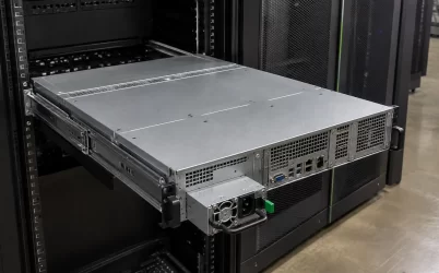
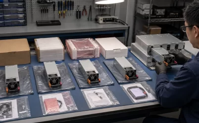
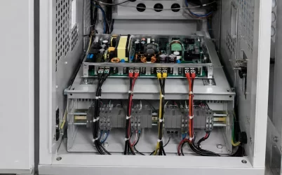
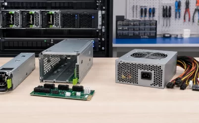
A 1200 watt server power supply does not have a universal pinout. Current search results associate the query with at least two distinct identities—DPS-1200FB A and DPS-1200MB A—and a PS_ON, ground, standby, or output contact claimed for one must not be transferred to the other. Read the complete PSU label, retain every suffix and revision marker, identify the connector face shown by each diagram, and record the host and mating power distribution board (PDB). Unless exact-model evidence supports the necessary contacts and startup behavior, do not bridge pins or energize the module.
Quick answer: 1200W is a rating class, not a pinout identity
The phrase “1200 watt server power supply pinout” is useful for finding candidate documents, but it does not identify an electrical interface. Treat DPS-1200FB A and DPS-1200MB A as separate models unless an authoritative manufacturer record explicitly establishes a relationship between them. Build an independent evidence packet for each identity, preserve connector orientation, and classify every proposed contact as documented, traced, measured, inferred, or unresolved. A forum diagram or modification PDF may suggest what to investigate, but it does not safely authorize a jumper, custom PDB, or standalone conversion for different hardware.
The search query merges two identities that the hardware does not
Search engines group pages through shared terms such as 1200W, server PSU, pinout, and PS_ON. That grouping is not an engineering equivalence statement. The strings DPS-1200FB A and DPS-1200MB A contain different base model identifiers, so they must remain separate even if photographs suggest similar metal enclosures or card-edge connectors.
The trailing letter also matters. It may identify a variant, revision, or other manufacturer-controlled distinction, but its exact meaning must come from applicable documentation rather than interpretation. Removing the suffix to make two filenames or diagrams appear consistent destroys information that may distinguish their interfaces.
| Evidence field | DPS-1200FB A packet | DPS-1200MB A packet | Reason for separation |
|---|---|---|---|
| Label identity | Photograph and literal transcription of the complete FB label | Photograph and literal transcription of the complete MB label | Similar wattage wording does not join different model strings |
| Revision information | All visible suffixes, revisions, and relevant manufacturing identifiers | All visible suffixes, revisions, and relevant manufacturing identifiers | A contact map may apply only to a particular hardware state |
| Connector evidence | Complete connector image with view direction and physical datums | Complete connector image with view direction and physical datums | Contact count or visual resemblance does not prove assignment equivalence |
| Platform context | Known host, cage, and mating PDB | Known host, cage, and mating PDB | The mating assembly may define control, sequencing, and management behavior |
| Pinout claims | Claims and evidence status recorded only in the FB packet | Claims and evidence status recorded only in the MB packet | Cross-copying creates a complete-looking but unsupported hybrid diagram |
Do not combine the packets merely because one contains a clearer photograph and the other contains a more detailed contact table. That would produce a third pinout belonging to neither documented model.
Create the evidence packets from the label outward
Begin with a photograph that shows the entire PSU label in focus. Transcribe the manufacturer name, complete model string, part numbers, revision marks, and any host-specific identifiers exactly as printed. Keep spaces, hyphens, and suffixes. If a seller photograph is the only available image, record that limitation and do not assume the shipped unit will carry the same label.
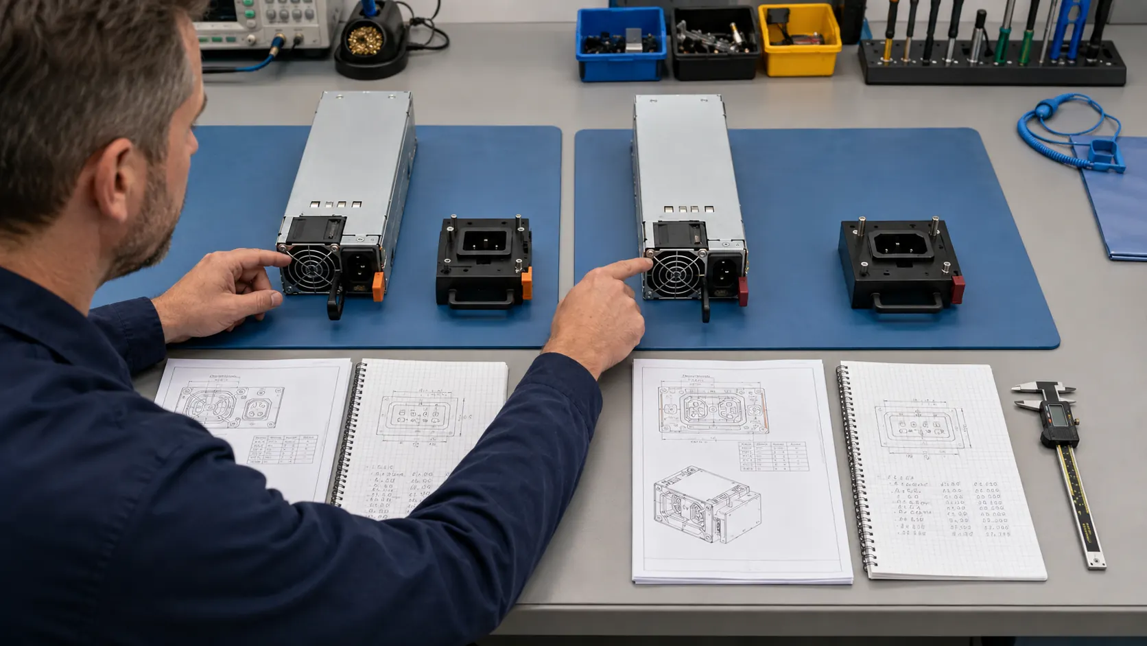
Next, capture the complete blind-mate connector without losing the surrounding mechanical references. The image should show the latch or handle side, top and bottom of the module, card-edge keys or connector partitions, and insertion direction. These features establish a coordinate system. A close-up containing contacts but no physical orientation cannot reliably be reconciled with another drawing.
The host relationship belongs in the same packet. Record the server or enclosure model, PSU bay or cage, and the board that receives the module. If the term PDB is ambiguous in the available material, first identify the server PDB hardware boundary. A server power distribution board may carry high-current output, standby power, enable controls, sense connections, current-sharing signals, and management communications. A pinout detached from that mating context may omit the behavior that makes the contacts usable.
Finally, give every document an explicit scope. A file named with “1200W PSU” may concern a family, a particular module, a host assembly, or a third-party conversion board. Record the title, publisher, revision or date when available, exact model named inside the document, connector view, and the claim the document actually supports. A useful filename does not expand the document’s authority.
A source can be authoritative yet still answer the wrong question
For Delta-identified hardware, the manufacturer’s power supply manuals and datasheets portal is the strongest supplied starting point for locating an exact-model record. The portal itself, however, is not proof of a contact assignment. The relevant file must name the applicable model or establish a documented relationship to it, and the drawing must define the same connector view being examined.
| Source type | What it may support | What it does not establish by itself |
|---|---|---|
| Exact-model manufacturer document | Published ratings, named contacts, interface behavior, and drawing orientation within its stated scope | Compatibility outside the named model, revision, or assembly |
| Server-OEM platform record | Approved option or replacement relationships for a specified host | A complete electrical pinout when the interface is not disclosed |
| PDB schematic or interface document | Mating contacts, host-side routing, signal destinations, and platform dependencies | Behavior of a different PSU or PDB revision |
| Third-party modification PDF | A hypothesis or starting point for the exact hardware it identifies | Manufacturer authorization, universal applicability, or safe transfer to another model |
| Forum post or photograph | A lead, observed label, physical clue, or reported behavior | A controlled pinout, verified signal limits, or supported conversion procedure |
| Continuity or voltage measurement | One observation on one specimen in one state | Complete signal function, safe logic level, sequencing, or cross-revision equivalence |
Source authority is claim-specific. A host service manual may be the best source for a supported spare while disclosing no contact map. A manufacturer datasheet may define module behavior without approving a particular server installation. A PDB drawing may reveal where a contact travels but not the limits inside the PSU. These records should be reconciled, not ranked as though one document can answer every question.
A correct contact name can still be attached to the wrong coordinate
Connector drawings are commonly viewed from either the PSU mating face or the PDB mating face. Those faces oppose each other in the assembled server, so a contact sequence may appear mirrored. A drawing can therefore contain correct electrical names and still be applied incorrectly if its viewing direction is lost.
Each diagram should state whether it shows the module side or mating-board side, whether the viewer is looking into the contacts or through the board, and where the top, latch, key, and insertion direction are located. Pin numbering should begin from a defined physical datum rather than an arbitrary left edge. If the source omits these coordinates, preserve the ambiguity instead of adding numbers that make the drawing look finished.
Contact geometry also carries functional clues without proving function. Wider or repeated contacts may be consistent with high-current paths, while shorter contacts may participate in insertion sequencing. Those observations can guide document review, but they cannot establish polarity, allowable current, timing, or signal purpose. The existing model-specific server PSU pinout verification workflow explains how to keep physical observation, documentation, measurement, and inference in separate evidence classes.
PS_ON and ground claims require more than a continuity result
Searchers often want the contact that starts the PSU and a ground contact to bridge it to. That request compresses several unresolved questions into two labels. The enable input may use a particular logic domain, reference, sequence, or host interlock. Although active-low enable conventions are common in power electronics, that convention does not prove the behavior of DPS-1200FB A, DPS-1200MB A, or another 1200W module.
“Ground” is equally imprecise. A server PSU interface may expose high-current output return, chassis or protective bonding structures, signal returns, sensing references, or contacts that appear connected under an unpowered continuity test. Their relationship and permitted use must come from exact documentation or controlled engineering evidence. Finding continuity to the metal chassis does not authorize using that point as the reference for an unidentified control input.
Bridging an unknown contact can connect an enable input to the wrong domain, short a standby source, disturb a current-sharing or remote-sense line, load a management bus, or bypass behavior normally implemented by the PDB. A module that starts after an improvised bridge is not thereby proven safe, regulated under load, or suitable for repeated standalone use.
Stop condition: If the full model identity, connector orientation, control reference, or required startup behavior remains unresolved, do not apply a jumper or energize exposed hardware. Mains-powered server PSUs should be investigated only by qualified personnel using an electrically safe, current-limited, and documented setup appropriate to the exact unit.
Let the available evidence set the action ceiling
Not every investigation requires the same level of disclosure. Evidence that is adequate to identify a spare may be inadequate for a custom PDB, while a partial reverse-engineering record may support further unpowered investigation without supporting energization. The intended action should therefore be written before deciding whether the collected evidence is sufficient.
| Proposed action | Evidence that must control the action | Reason to stop |
|---|---|---|
| Identify a module or replacement candidate | Complete label identity and an authoritative model or host relationship | The candidate is identified only by 1200W, appearance, or a shortened part number |
| Organize an unpowered bench investigation | Exact specimen record, complete connector coordinates, safe isolation procedure, and explicit unknown-contact list | The unit, connector view, or safe handling boundary is uncertain |
| Design a mating PDB or adapter | Verified power contacts, signal definitions and limits, sequencing, mating geometry, current paths, protection responsibilities, and thermal conditions | The proposed design depends on copied, inferred, or cross-model contacts |
| Energize or operate outside the original host | Exact-model startup requirements, safe input arrangement, verified output and control interface, load plan, protection, and qualified procedure | PS_ON, return, standby behavior, or another required function remains unresolved |
This action ceiling prevents one valid observation from being promoted into a much broader claim. A label photograph can identify the search target; it cannot define PS_ON. A manufacturer contact name may establish function; it does not automatically define the custom adapter’s current capacity or insertion behavior. A successful no-load startup does not prove regulation, protection, cooling, or safe operation at useful output.
An unresolved pinout is a valid search result
A useful investigation does not need to end with every contact named. For each of the two search-result identities, preserve the exact label, source documents, connector orientation, host and PDB context, and a contact-level status vocabulary: manufacturer-documented, platform-documented, physically traced, measured, inferred, conflicting, or unresolved. Include the proposed action and state whether the evidence permits only identification, further bench investigation, integration design, or energization.
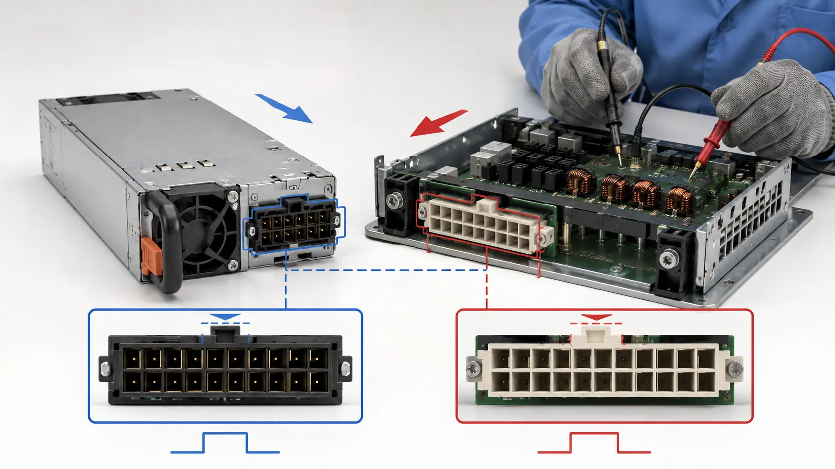
If the DPS-1200FB A packet contains a third-party diagram but no exact-model primary record, say so. If the DPS-1200MB A packet contains a connector photograph without an orientation reference, retain that limitation. If two sources conflict, do not choose the assignment that appears more convenient. Keep both claims attached to their sources until the discrepancy is resolved through authoritative documentation or a properly controlled investigation.
The defensible answer to a 1200 watt server power supply pinout search may therefore be that no supported contact map is available from the evidence in hand. That outcome is more useful than merging DPS-1200FB A and DPS-1200MB A into a universal diagram. It tells the engineer exactly which identity, document, mating assembly, coordinate, or electrical behavior must be obtained before the next action becomes justified.