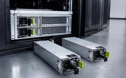
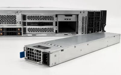
A 1500W 80 PLUS Titanium server PSU is not a universal upgrade for a server that happens to need more power. It is a high-capacity module whose usefulness depends on the host chassis, power-distribution board, input service, redundancy architecture, cooling path, and documented interface. The right question is not whether 1500W exceeds the system’s estimated draw. It is whether the completed platform can use that module safely and continue operating acceptably after one supply, one input feed, or one cooling condition is lost.
For a new server design, begin with the approved chassis and PDB rather than the wattage printed on a candidate module. For a replacement, identify the installed module and its mating hardware before treating output capacity or efficiency class as a substitute for compatibility evidence.
The first question is what one surviving module must carry
A 1500W Titanium PSU can be appropriate for dense compute, storage, or accelerator configurations, but its nameplate rating does not establish replacement compatibility or protected capacity. Confirm the exact chassis bay, blind-mate connector, PDB, input-voltage range, power-cord and branch-circuit arrangement, firmware support, airflow direction, and redundancy policy. Then evaluate the surviving-power condition: in a 1+1 design, one remaining supply must carry the defined load inside its documented operating limits. Efficiency may reduce conversion loss under the applicable test conditions, but it does not solve an incompatible mechanical interface, an overloaded input path, or an unverified current-sharing arrangement.
Separate the three meanings of “1500W”
Procurement discussions often merge three different quantities into one number. The module rating is the capability published for a particular PSU under specified input and environmental conditions. System demand is the DC power the completed server consumes across defined operating states. Protected capacity is the load that remains supportable after the failure scenario the architecture promises to tolerate. These quantities may be related, but they are not interchangeable.
Consider a hypothetical dual-supply server. If each module is rated for 1500W under the intended input condition, a healthy pair may share a load substantially below the arithmetic sum of their labels. Under a one-module failure, the surviving path must support the required operating load by itself. That evaluation also has to include any policy that reduces processor or accelerator power after a fault, the state of storage and fans, and the actual input condition. A design described as redundant should state whether it protects full performance, a managed reduced-performance state, or only orderly shutdown.
Do not convert a two-module 1+1 arrangement into a claimed 3000W protected system without documentation. That would confuse installed module capacity with N+1 service capacity. Conversely, a single 1500W module can be more than adequate for a nonredundant appliance, while still being unsuitable for a chassis designed around hot-plug PDB distribution.
Take two hypothetical host configurations to expose the boundary. One requires 1180W DC during its defined post-fault operating state; the other requires 1570W DC to maintain full service. A pair of modules each labeled 1500W cannot support the second configuration as full-performance 1+1 under the simplified nominal comparison, because one survivor is below the stated need. The first configuration may fit, but only after checking the exact module’s usable output at the installed input and temperature, transient behavior, PDB limits, and host policy. These example loads are not measurements of any Powernexu product or customer system. They show why a capacity claim needs a named failure state.
Start with the chassis-to-PDB interface
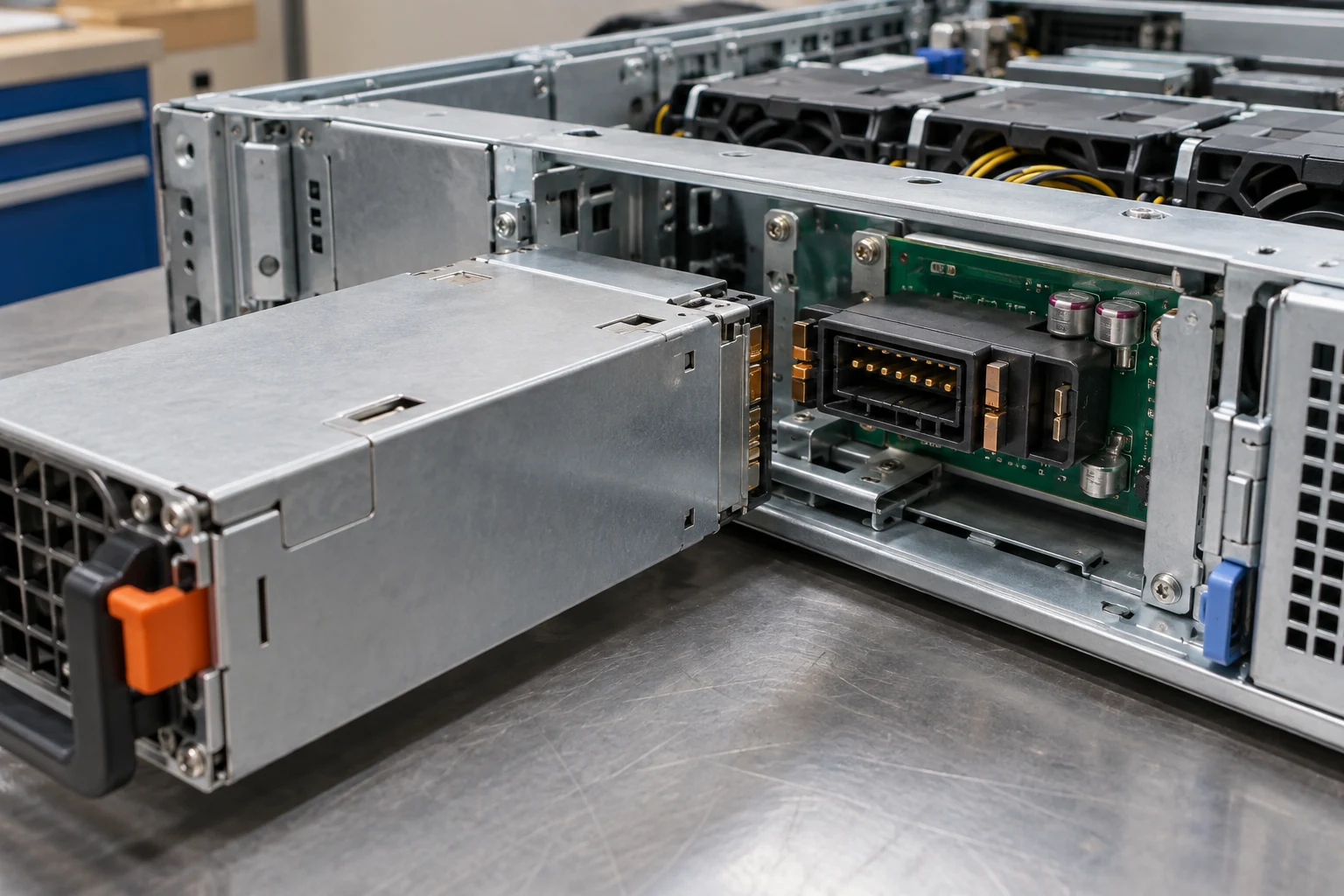
Hot-plug server PSUs are part of an assembly. The module slides into a cage, mates with mechanical guides and a high-current connector, and usually connects through a PDB that distributes output power and control signals. Dimensions, latch location, handle geometry, airflow direction, connector pin assignment, enable behavior, standby power, telemetry, and fault signaling are all part of the interface. A module that looks similar from the rear can fail to seat, fail to communicate, or create an unsafe electrical mismatch.
Build an evidence packet before comparing candidate supplies. It should include the host or chassis model, the existing PSU part number, photographs of labels and mating connectors, PDB part number, server vendor documentation, input-power requirement, and any approved replacement list. If the platform is custom, add the mechanical drawing, connector definition, expected output rails, control and sense requirements, cooling layout, and firmware behavior. This record is far more useful than a search for a visually similar “1500W server power supply.”
Connector appearance is especially weak evidence. High-current blind-mate systems may use proprietary keying, staggered contacts, sequencing, remote sense, management signaling, or pre-charge behavior. An adapter can make two shapes meet while leaving those electrical functions unresolved. Use an adapter only when its complete electrical and thermal behavior is documented for the exact source module and host assembly.
Read the Titanium label in its operating context
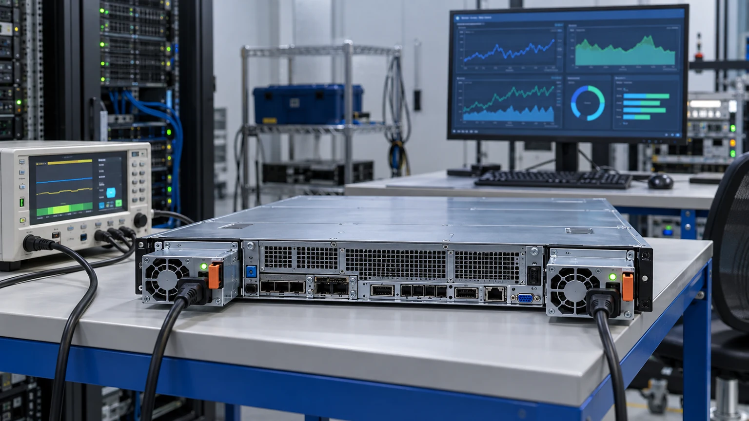
80 PLUS Titanium is an efficiency classification, not an interoperability standard. It indicates that a tested power supply met the program’s efficiency requirements at specified load points and input conditions. It does not confirm the DC connector, form factor, cooling behavior, line-cord requirement, output capability at a particular ambient temperature, or support in a particular server. When comparing modules, retain the test context rather than turning an efficiency badge into a general performance claim.
At a given DC load, conversion loss is the difference between input power and delivered output power. Lower loss can reduce heat produced inside the supply, but the resulting system benefit depends on workload, inlet temperature, fan control, redundancy state, and the upstream facility path. A server that spends most of its time lightly loaded may not see the same practical difference as one operating near a sustained higher load. The complete power path also includes upstream conversion and distribution equipment; a PSU efficiency class alone does not characterize facility energy use.
Use the certification claim only if it can be tied to the exact model. A marketplace title, a generic product family page, or a photo of a label is not enough to establish a particular module’s certification, input rating, or revision. Preserve the manufacturer documentation and, where applicable, the certification record alongside the approved bill of materials.
Map the AC path before deployment
A higher-capacity server PSU can move the limiting constraint upstream. Verify the nominal input voltage and permitted range published for the exact module, then trace the path through the inlet, cable, rack PDU, branch circuit, and source redundancy arrangement. A module may expose a high output rating only under certain input conditions. Do not assume the same result from a different regional supply, a different PDU outlet, or a reduced-voltage service.
For redundant systems, document source separation as well as module count. Two PSUs connected to the same upstream breaker, PDU, or source transfer path may provide tolerance for a module failure but not for every power-distribution failure. Where the availability objective requires it, route the feeds through independently managed source paths and label them clearly. That design decision should be reviewed with the facility and rack-power teams, not inferred from the server’s rear-panel PSU count.
A useful commissioning worksheet records input source identification, measured voltage at installation, cord and plug type, PDU outlet assignment, breaker information, and the intended failure-domain relationship. The worksheet should also identify the person responsible for approving any change to the server power policy. This prevents a later service event from silently collapsing the planned A/B feed arrangement.
Use workload states, not a single average reading
Capacity planning for a 1500W module should describe the server states that matter. Those may include idle, operating-system boot, storage initialization, accelerator initialization, steady compute, firmware updates, fan ramp events, and the expected behavior after one PSU is removed. A single wall-power snapshot can be useful, but it does not represent every transition or distinguish AC input power from DC load.
Start with a documented hardware population: processors, memory, accelerators, storage, NICs, fans, expansion cards, and externally powered options. Define the allowed workload and power-management settings. Then collect telemetry or controlled measurements for the relevant states. Treat measurement limits honestly. An input meter includes PSU conversion loss; a BMC value may not include every load; a short sample may miss an initialization event. The purpose is to establish a bounded operating envelope, not to manufacture a precise number from incomplete data.
When a failure policy includes continued operation on one supply, repeat the relevant observations in that state under controlled conditions. Review event logs for current-sharing, input loss, over-temperature, and module fault indications. If the platform reduces performance after a supply failure, verify that behavior is intentional, visible to operations staff, and compatible with the service objective.
Cooling and serviceability decide whether the installation remains dependable
A 1500W-class module can concentrate substantial conversion and airflow activity into a small rear-bay volume. Confirm the chassis airflow direction, blanking requirements, fan zoning, permitted inlet conditions, and clearance needed to remove a failed module. A missing blank, obstructed rear path, or incompatible fan policy can disturb the cooling design even when the supply electrically powers on.
Service procedures should cover more than swapping a module. Identify which alarms appear in the BMC or platform manager, whether replacement requires a matching firmware revision, how the team verifies load sharing after insertion, and how A/B feed labels are preserved. Keep a verified spare strategy: an unqualified “same wattage” spare can lengthen an outage when its connector, airflow, or management behavior differs from the installed assembly.
For a structured overview of redundant capacity and failure-domain decisions, see server dual power supply protection. For broader context on matching PSU capacity to the server architecture, see server power supply wattage.
Three different outcomes for a 1500W decision
| Observed or documented condition | What it means for the 1500W proposal |
|---|---|
| Exact module, PDB, input service, and fault-state load are approved and verified | The configuration has a defensible basis for the stated service mode, subject to its documented limits. |
| Normal load fits, but the one-module state requires workload reduction | Describe the protected service as a managed reduced-performance state, not full-performance 1+1. |
| The connector, firmware, or available output at the installed input is unresolved | Do not approve a replacement solely because its rating and efficiency tier look attractive. |
The release record should name the actual module and revision, chassis and PDB, input service, installed component population, measured workload states, fault policy, and approved spare. If the evidence supports only a reduced-performance mode, operations should know which workloads continue and which are shed when one module fails. This is a more useful conclusion than calling every dual-module 1500W installation “redundant.”