“High reliability” is useful in an industrial power-supply specification only when it describes a failure behavior the machine owner can verify. A large MTBF number may be relevant, but it does not tell an integrator when wear-out is likely, whether a failed output will shut down safely, or how quickly a line can return to service. To select a high-reliability industrial power supply, define the mission duration, operating environment, unacceptable failure modes, detection method, and repair plan. Then ask for model-specific evidence under comparable conditions.
This article separates three questions that are often collapsed into one marketing claim: How frequently might random failures occur in a population? How long should a unit remain serviceable under its stated conditions? What happens to production when a unit actually fails? Each question calls for different evidence and can lead to a different design decision.
An MTBF figure is a population statistic, not a replacement date
Mean time between failures, or MTBF, is commonly used to describe an expected rate of random failures for a repairable population under defined assumptions. It is not a promise that one supply will operate until that many hours have elapsed. Nor does it describe every wear-out mechanism. A comparison is meaningful only when the prediction method, ambient temperature, electrical load, operating profile, component assumptions, and definition of failure are comparable.
The PULS application note on MTBF and service lifetime distinguishes reliability calculations from the useful-life question. For an industrial buyer, the practical implication is simple: request both the method behind a statistical reliability claim and the conditions used to estimate service life. If a vendor supplies only a headline MTBF, it is reasonable to ask what the number excludes.
Imagine two candidate units with different published MTBF values. One is rated under a cool, light-load model; the other provides a lower number under a hotter, more demanding operating condition. The larger number cannot be called the better choice without normalizing the assumptions. Ask whether the specified input, output load, enclosure temperature, cooling orientation, and duty cycle resemble the installed machine. A supplier that can explain its assumptions may provide more usable evidence than one that offers a larger unexplained number.
Do not convert MTBF into a preventive replacement interval by simple arithmetic. Replacement planning should also consider components that age, expected mission duration, downtime cost, spare availability, and signs of deterioration that can be monitored. The machine owner may choose a conservative replacement policy, but that policy should be tied to its risk and maintenance data rather than to a misunderstood single statistic.
Lifetime lives in the installed temperature profile
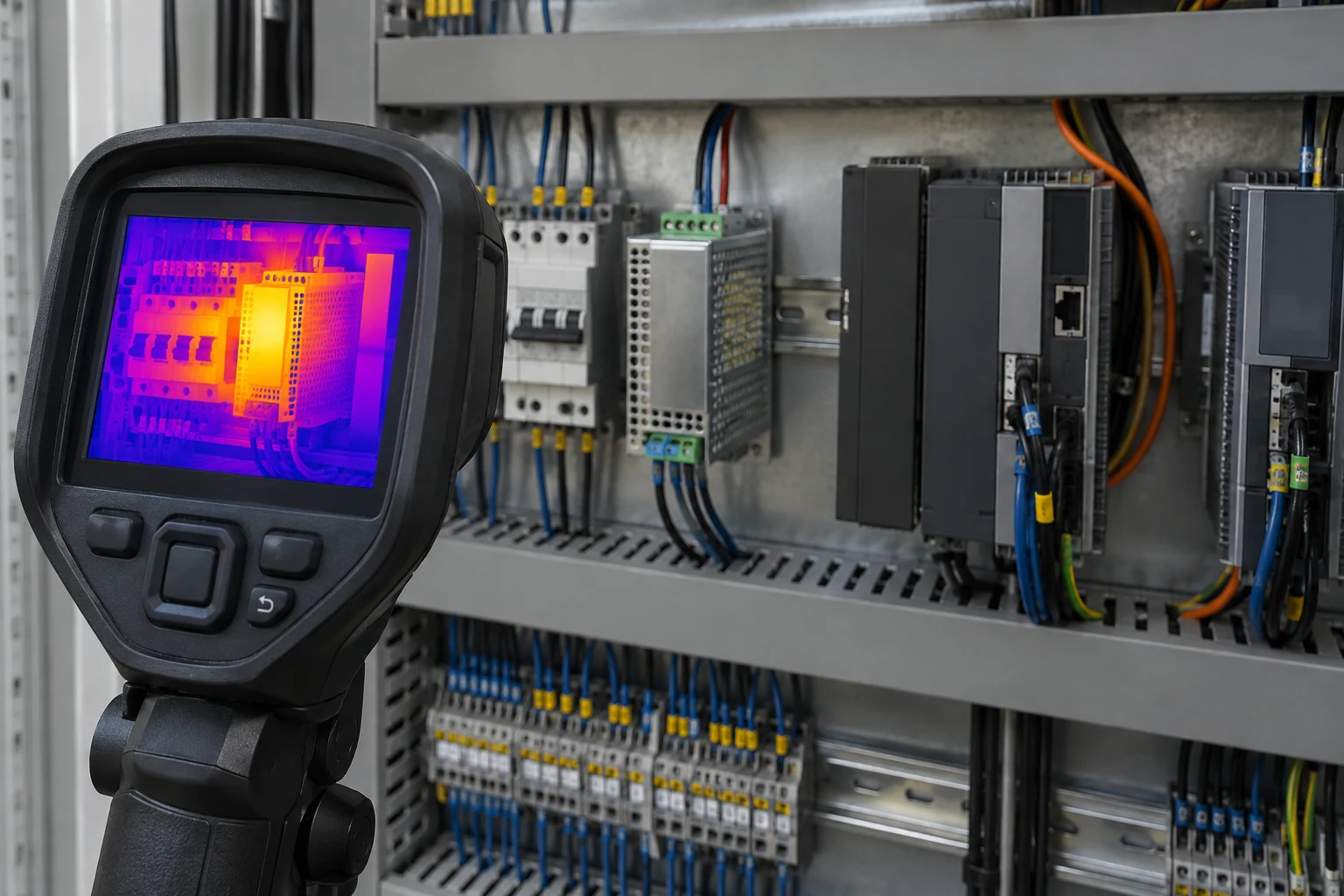
An industrial power supply experiences the temperature inside its actual cabinet, not the temperature written on a facility thermostat. Internal losses, adjacent drives, sunlit enclosures, restricted vents, and changes in fan or filter condition can all raise local temperature. A supply that is suitable at one ambient condition may need derating or different cooling at another. The exact derating and lifetime data must come from the model’s documentation; no universal temperature allowance can replace it.
Map the operating cycle rather than recording one afternoon reading. Include startup, steady production, peak actuator activity, idle or overnight conditions, and any seasonal condition relevant to the site. Temperature logging near the supply inlet can reveal a cabinet hot spot that a room sensor misses. Where the supplier provides component-temperature or lifetime curves, compare them with a representative measured profile. Record sensor location and machine state with the data so later engineers can interpret it.
Electrolytic capacitors, fans, relays, and other parts may set different wear-out limits depending on the design. It is inaccurate to name one universal weak link for every industrial supply. Ask the manufacturer which components dominate the life assessment for the exact model and whether the expected installation changes that assessment. A sealed converter, a fan-cooled enclosed unit, and a DIN-rail supply in a crowded cabinet may have very different maintenance implications.
The output load profile also matters. A process machine that draws modest power most of the day but repeatedly starts motors, valves, or heaters may stress the source differently from a stable instrumentation rack. The supply’s overload, inrush, and thermal responses must match those events. A laboratory life estimate made at a fixed load may not represent the combination of temperature and cycling in the plant.
Reliability can fail at the terminals before the converter fails
Even a well-designed converter cannot compensate for a loose termination, undersized conductor, contaminated connector, or incorrect protective-earth connection. The installed power path includes upstream protection, wiring, terminals, load branches, and grounding. These interfaces may be disturbed during maintenance or affected by vibration and contamination. Treat their inspection as part of the reliability plan rather than an unrelated electrical housekeeping task.
Look for a credible failure path from each interface to the protected load. A rising contact resistance can create heat and voltage loss without producing an immediate hard fault. A shared return conductor can couple an actuator event into a controller supply. A branch without suitable protection may leave wiring exposed to fault energy even when the converter has electronic current limiting. Exact protection coordination requires the documented device behavior and local electrical design, not a generic assertion that the supply has “short-circuit protection.”
For a new machine, record the wiring diagram and expected current at each branch. For an operating machine, use approved inspection and measurement procedures; do not improvise live cabinet work. If a fault appears only at certain machine positions or during vibration, include the physical installation in the diagnosis. Replacing the PSU repeatedly without examining terminals and load wiring can preserve the true cause.
Connector and terminal checks should also survive procurement changes. A replacement with the same nominal output may have a different terminal style, torque requirement, wire accommodation, or protective response. The spare-part record needs the exact approved model and installation instructions, not just voltage and wattage.
Define what the machine should do when DC power degrades
A high-reliability design is not necessarily one that never stops. Some industrial processes must shut down predictably when a control rail leaves its allowed range. Others must ride through a specified short interruption, retain state, or continue on a redundant source. Write the required behavior in machine terms before choosing a PSU architecture. “No nuisance reset during valve actuation” and “safe output de-energization after supply failure” are different requirements and may call for different tests.
Trace the failure boundary. A redundant pair may cover failure of one converter, but not a common upstream breaker, shared wiring error, or overloaded output distribution. An energy-storage stage may bridge an interruption, but its duration and recharge behavior must be established for the actual load. A controller alarm that reports low voltage after a reset may be too late for a process that needs an orderly stop. Detection timing belongs in the acceptance criteria.
Use a fault matrix with plain-language outcomes. For each credible event, identify the affected machine function, the expected electrical response, operator indication, and recovery action. Candidate events may include an input dip, output overload, disconnected sensor branch, blocked ventilation, failed fan if present, and loss of one redundant supply. The list should be tailored to the machine; it is not a universal certification test. Some events must be evaluated analytically because inducing them on an operating production line would be unsafe.
A service plan completes the behavior definition. If replacement requires stopping a cabinet and waiting for qualified personnel, the expected downtime may dominate availability even with a low random failure rate. Where fast replacement is required, design access, labeling, spare storage, isolation, and post-replacement checks before deployment. Availability is an outcome of both failure rate and restoration process, not a property printed on the PSU alone.

A comparison that changes the purchasing decision
Consider a hypothetical packaging line with a 24V control supply. Its controller must avoid resetting when a solenoid bank energizes, but a sustained DC undervoltage must lead to a known safe stop and a visible alarm. The cabinet is hot during summer production, and a maintenance technician can reach the supply only during a planned line pause. These are example requirements, not a Powernexu customer case or a claim about a particular model.
Candidate A offers an impressive MTBF statement but no clear operating condition for that value. Candidate B provides a lower figure with defined temperature and load assumptions, a model-specific derating curve, documented overload recovery, and an approved spare process. Neither candidate is automatically superior. The buyer can compare both against the cabinet’s measured temperature profile, verify transient behavior with the solenoid load, and estimate the operational consequence of a failure. The apparent numerical ranking may change once the actual machine conditions are applied.
Suppose a third candidate survives a bench test but the installed cable length causes a controller input dip during solenoid activation. The supply itself may be sound; the distribution path or local energy storage may be the limiting element. A reliability purchase cannot be closed by replacing the PSU with a larger label while leaving that measured mechanism unexplained. The corrective action should follow the evidence from the controller input back to the source.
This comparison also shapes the request for quotation. Include the input source, required DC rail and load profile, cabinet temperature, mounting and cooling arrangement, process failure behavior, applicable compliance needs, mission duration, and service target. Ask the supplier to identify the exact model and the documents that support each requirement. A short, specific RFQ often reveals more than a long generic feature checklist.
Prove the operating envelope without inventing a reliability score
Qualification should connect each requirement to a measurement or document. Confirm output regulation at the load, startup and transient response under representative machine sequences, sustained thermal behavior, protective response for the relevant fault cases, and recovery after the fault is removed. Check the intended input extremes and any documented derating boundary. Where safety or EMC approval is required, verify the certificate or report for the exact model and applicable configuration rather than assuming the whole product family shares it.
Separate evidence from inference in the release record. A supplier datasheet can establish a published operating limit. A site temperature log can establish the cabinet condition observed during a specific interval. A bench test can establish behavior for the tested machine configuration. None of these alone proves a universal failure rate in service. Describe what each item actually supports and note remaining assumptions that operations should monitor.
For related selection questions, the industrial power supply selection article covers package and basic electrical fit. This reliability discussion starts after those basics: it asks whether the machine can sustain its mission, detect an unacceptable degradation, and recover in time. The distinction keeps the two articles useful for different decisions.
A final service handoff should contain the approved supply revision, wiring and protection drawing, temperature and load records, test outcomes, alarm behavior, spare identifier, and replacement instructions. Review the record when the cabinet changes, the process duty increases, or field failures reveal a new pattern. A defensible high-reliability choice is an evidence-backed operating agreement between the converter, the machine, and the people who maintain it.