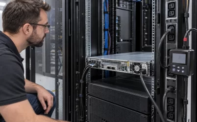
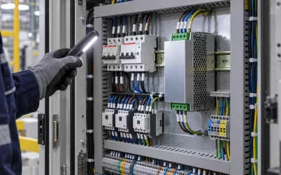
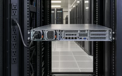
Server power supply branch circuit requirements begin upstream of the PSU: the facility branch, rack PDU, outlet, cord, and inlet must all support the server’s input under the operating and failure conditions the site expects. A module’s DC wattage alone cannot size a branch circuit. Plan from the exact PSU input data, measured or qualified rack load, PDU and cord ratings, and the behavior of redundant feeds after one path is lost. A licensed electrical professional should apply the governing local code and installation documents to the final circuit design.
The easily missed case is a rack that looks lightly loaded while A and B feeds share power. After one feed fails, surviving equipment may shift more input current onto the remaining path. A branch plan that records only today’s balanced current can therefore understate the current the surviving branch must carry. The required comparison is between the load that actually moves and the usable rating of every component in that path.
Start at the PSU inlet and work toward the panel
For each server, identify the PSU model and revision, supported input voltage and frequency, maximum documented input current, inlet type, cord requirement, and any output derating at the site’s supply voltage. If the chassis supports several PSU options, use the option actually installed or formally approved. A generic server nameplate may describe a broader configuration than the rack contains, while one short meter reading may miss a future workload or fan state. Keep both the manufacturer data and the measured profile, with their different purposes clearly labeled.
Trace the physical path backward: server inlet, line cord, rack PDU outlet, PDU internal bank or protective device where applicable, PDU input cord or whip, upstream branch circuit, and source panel. At each point, record the exact rating and installation condition. A high-rated PSU cannot raise the current capability of a smaller connector, cord, outlet, PDU bank, or branch. Conversely, a large branch breaker does not make every downstream outlet suitable for that current.
Do not infer branch capacity by multiplying a PSU’s DC output label by the number of servers. The AC current depends on input voltage, actual DC load, conversion efficiency, power factor, and the host’s operating policy. Manufacturer maximum input current can be important for design screening; measured current helps describe deployed demand. The electrical designer decides which values and demand rules apply to the installation and jurisdiction.
Keep a one-line diagram or rack schedule that shows the source path for each cord. Color-coded cables help operations, but a color is not proof that feeds are electrically independent. Confirm the upstream panel and circuit identifiers in the site records before describing A and B as separate failure domains.
What the surviving branch sees after a feed loss
Consider four hypothetical dual-cord servers at one rack voltage. In normal operation each server draws a total of 2A AC, divided about equally between A and B, so each branch sees approximately 4A from the group. If B disappears and the hosts continue the same workload on A, the group could place about 8A on A. These values are an illustration of load transfer, not a breaker-sizing recommendation. Actual current may differ because PSU efficiency, fan speed, workload policy, and recovery behavior can change after the event.
Now repeat the thought experiment for the entire PDU, not just the four servers. Include network switches, storage shelves, management equipment, and any other loads connected to the surviving branch. Some devices may have a single cord and will not transfer; others may switch through an automatic transfer device; still others may stop. The branch-current budget should reflect those behaviors explicitly. A rack label saying “A/B redundant” does not answer which load moves when a particular circuit opens.
Test the stated redundancy boundary using approved site procedures. De-energizing a live branch casually can interrupt services or create an unsafe condition. Facility and platform owners should define a controlled test that observes current on the surviving path, alarms, server performance, and recovery. When a full live test is not practical, use documented equipment behavior and conservative design analysis, and identify the untested assumption.
The same exercise can reveal a common point upstream. Two rack PDUs connected to separate outlets of one branch, or to different branches in the same maintenance domain, may not provide the source separation the availability plan expects. “Dual cord” is a physical description; “survives the loss of this circuit or source” is a testable service requirement.

Where the rating changes along a rack path
A rack PDU may have an input rating, multiple outlet types, internal branch groups, and specific installation instructions. Use its nameplate and manual, not a generic circuit assumption. For example, Vertiv’s rack PDU guidance explains that appropriately sized building branch protection and the PDU nameplate must be considered together. Its examples are product and jurisdiction dependent; they are not a universal rule for every Powernexu installation.
Follow the same discipline at the line cord and receptacle. The cord’s connector family, conductor rating, length, routing, strain relief, and environmental suitability matter. A plug that mechanically fits an outlet does not establish that the PDU, cord, and PSU are an approved combination. Confirm the server vendor’s cord instructions and the site electrical standard, especially when changing input voltage or moving a rack between regions.
Within a PDU, an individual outlet or bank can have a lower applicable limit than the total device input. A rack can remain below the PDU’s aggregate rating while one bank is overloaded. Metering may be available by outlet, bank, or whole PDU; know which level the display represents. Record circuit identifiers beside the measurement so the operations team can match an alarm to the loads it affects.
Three-phase distribution adds another boundary. Servers may be connected unevenly across phase pairs or PDU banks, causing one phase or group to approach its limit before the rack total suggests a problem. The relevant topology is site-specific. Have the facility designer review phase assignment and neutral considerations where applicable; do not reduce a three-phase installation to a simple sum of outlet watts.
Startup is a separate stress from steady rack demand
When power returns to a rack, many PSUs, fans, drives, and control boards may start within a short interval. Their input behavior can differ from steady-state current. A branch that carries normal production load may still trip on a poorly sequenced restart, depending on the equipment and protective devices. Obtain model-specific inrush information and PDU or server startup guidance where this matters to the site.
Do not treat a high inrush figure as if it flows continuously, and do not dismiss it because it is brief. Protective-device response depends on duration, magnitude, the device’s characteristics, and the number of loads starting together. Avoid inventing a universal “safe number of servers per circuit.” A facility engineer can compare the actual starting sequence with the selected breaker and PDU documentation.
Switched rack PDUs or server-management policies may support staged power-up. A staged sequence can reduce coincident starting current, but the feature must be configured, retained after maintenance, and tested. If all outlets revert to immediate-on after a PDU replacement or reset, the original mitigation may disappear. Put the intended sequence in the rack runbook and configuration backup.
Also decide what occurs after one source returns. Some dual-input equipment may rebalance rapidly; other platforms may apply a control delay or load policy. Observe the transition because it can move current between branches again. “Power restored” is not the end of a source-failure test if the return event itself causes a trip or host reset.
Measure the rack as it operates, then design for what it must survive
Collect interval current or energy data from the level that matters: branch panel, PDU input, internal bank, or outlet. A whole-rack number helps trend demand but can conceal a bank imbalance. A server BMC number may describe internal power rather than the AC current seen by the branch. Pair electrical measurements with a rack inventory and workload notes so spikes can be traced to actual activity.
Separate ordinary operating demand, documented maximum demand, and the one-path-surviving state. For a growing rack, include planned hardware additions and the date at which the circuit budget must be revisited. A branch schedule frozen before the next storage shelf or accelerator node is installed quickly loses value. Change control should require checking both normal and failure-state budgets whenever loads or cord assignments change.
If the site uses an N+1 UPS or upstream generator, do not assume that arrangement automatically protects every rack branch. Verify transfer behavior, source capacity, and the actual PDU feed mapping. The critical question is which load remains connected to which source during a specific failure or maintenance action. The server’s redundant modules are only one layer in that path.
For the PSU-side voltage and cord matching problem, see matching server PSU input to rack voltage. This article addresses the branch budget and transfer path after those input compatibility checks are known.

A rack schedule that an electrician and operator can both use
The handoff should identify each server and PSU option; its two cord destinations; PDU model, bank, and outlet; branch and panel identifiers; input voltage; relevant equipment ratings; measured normal current; anticipated growth; and modeled or tested surviving-path load. Include the protective-device and installation references chosen by the facility designer. Record which measurements are whole-PDU totals and which are outlet or bank readings.
Add operational instructions: how to recognize an approaching limit, which load moves when a branch fails, how staged power-up is maintained, and who approves a cord move. A simple spreadsheet can support the schedule, but the physical labels and electrical drawings must agree with it. After a rack change, compare actual cord positions and meter readings with the record; otherwise the calculation may be precise for a wiring arrangement that no longer exists.
The branch circuit requirement is thus a property of the complete installation and its expected fault states. The PSU supplies the input limits and operating behavior. The rack PDU and cords define downstream connection limits. The facility design establishes the branch and protective devices. A sound deployment brings those records together before the next server is plugged in, and revisits them when the rack’s load or source path changes.