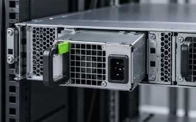
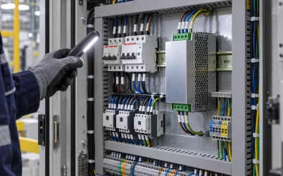
A 750W 12V server power supply can deliver useful capacity only if the server’s distribution path carries that power to the loads without excessive voltage drop, heating, or unstable behavior during fast changes in demand. The 750W label describes a module capability under its documented conditions; it does not establish that a particular PDB, connector, harness, or chassis is suitable. For a replacement, begin with the host’s approved module and distribution hardware. For a new design, treat the 12V path from PSU contacts to board inputs as part of the power system.
This distinction matters most in compact servers. The PSU may pass an output test at its own terminals while a processor board or storage backplane sees a different voltage during startup or peak activity. A useful qualification plan therefore measures where the load receives power, identifies every current-carrying interface, and checks the operating states that the deployed server will actually encounter.
What 750W implies for a 12V distribution path
Dividing 750W by 12V gives 62.5A. That is an idealized current at the stated output power and nominal voltage, not a claim about any particular product’s continuous current rating. The exact rated current, output-voltage tolerance, input conditions, cooling requirement, and derating behavior must come from the candidate module’s documentation. Still, the arithmetic reveals why contact resistance and copper geometry matter: a small resistance in a path carrying tens of amperes can cause meaningful loss.
Consider a purely hypothetical 10 milliohm resistance across the combined connector, board, and wiring path at 50A. Ohm’s law gives a 0.5V drop, and I squared R gives 25W dissipated in that path. Those figures are not Powernexu product measurements or recommended design limits. They illustrate the questions to ask: how much of the loss occurs at one contact, where does the heat go, and what voltage reaches the load under the worst supported operating condition? At 12V, a half-volt difference is large enough to deserve engineering attention, even when the PSU itself remains within specification.
Use an appropriate measurement method. A handheld meter can help characterize a steady condition; an instrument with sufficient bandwidth may be needed to observe a short load transition. Measure across the complete path and, when safe and practical, across individual connectors or board sections. Four-wire resistance measurements on an unpowered assembly can complement live voltage-drop checks. Record the current and temperature at the same time, because resistance and cooling conditions influence the result.
The PDB is where a compatible module can become an incompatible system
Many servers place a power-distribution board between a removable PSU and the loads. Depending on the platform, that board may combine or isolate outputs, route standby power, carry control and sense signals, distribute high-current 12V power, and connect to downstream converters. Its exact functions vary. A module that slides into the bay is not proven compatible until the host and PDB documentation confirm the electrical contacts, mechanical alignment, signal definitions, management behavior, and approved part relationship.
For a field replacement, capture the chassis model and revision, existing PSU part number, PDB identifier, and any approved substitution notice. Photographs can help identify the installed hardware, but a similar housing or latch does not prove the blind-mate interface is equivalent. For a new integration, obtain the actual mating drawings and pin definitions before routing high-current copper or defining controls. Treat a missing interface document as an unresolved design item, not as permission to assume a familiar pinout.
Inspect how current divides among contacts and conductors. A connector’s total current rating cannot safely be interpreted as one arbitrary number of amps per visible pin without its manufacturer’s conditions. Mated contact quality, temperature rise, allowable wire gauge, plating, airflow, and current-sharing between parallel contacts all matter. Uneven resistance can concentrate heat in one interface even when the aggregate path seems adequately sized.
A good review follows the physical route: PSU output contacts, mating connector, PDB copper and protection, harness or busbar, motherboard input, and local point-of-load converters. At each boundary, ask for the rated operating condition and the method used to verify it. This physical tracing gives the phrase “750W 12V server power supply” a concrete meaning in the finished chassis.
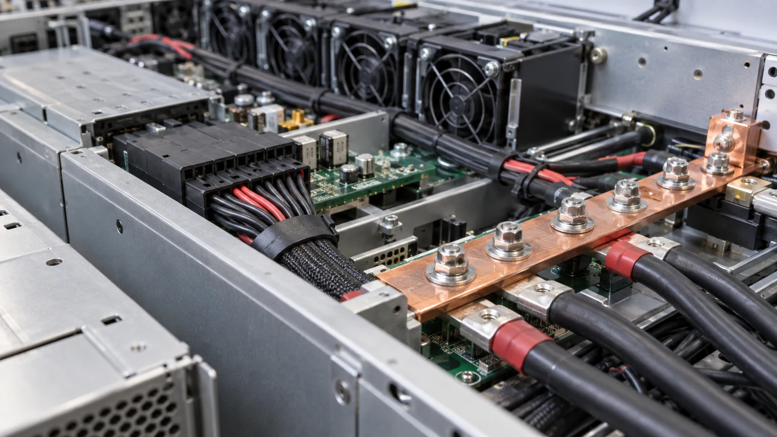
Do not use the PSU’s output reading as the load’s voltage proof
Remote sense, when provided and supported by the complete system, can compensate for some distribution loss. It cannot remove heat from a resistive connector or turn an undersized harness into a suitable one. Incorrect sense wiring can also create a control problem. Follow the specific module and PDB documentation for sense connections and permissible compensation rather than adding sense leads as an improvised fix for a voltage-drop finding.
Map the voltage limits of the downstream equipment before deciding where to measure. A motherboard may convert 12V into several lower rails, while drives, fans, or cards may receive power through different branches. The critical measurement point is the input of the affected load or converter, not whichever location is easiest to reach. A single voltage reading at an unloaded PDB test point can miss both branch loss and a brief excursion during activity.
Separate the continuous operating case from the changing-load case. Steady current can reveal resistive loss and thermal rise. Fast CPU or accelerator changes can expose interactions among PSU response, PDB impedance, bulk capacitance, cabling, and local conversion. The relevant pass criteria come from the platform and load specifications; they should not be invented from the PSU wattage. Capture waveforms with the probe reference and measurement bandwidth documented, or a misleading trace may send the investigation in the wrong direction.
Startup deserves its own observation. Fans, drives, management circuits, and board converters may not energize in the same order. A system that runs after a manual restart may still fail from a cold start or after AC power returns. Check sequencing and inrush behavior with the intended hardware population, and verify that any protective response recovers in the manner required by the server. Avoid repeatedly cycling an unexplained fault merely to obtain a successful boot.
A worked example: the same module, two different outcomes
Imagine two hypothetical 12V server assemblies using a candidate PSU whose documented operating envelope supports their input and thermal conditions. Both draw a measured 480W from the 12V output during a sustained workload. In the first assembly, a short, documented distribution path keeps board-input voltage within the board’s stated limits throughout the workload and during authorized load transitions. Connector temperature remains within the applicable component rating. That result supports this particular configuration, subject to the remaining platform checks.
The second assembly draws the same 480W but uses a different PDB revision and a longer harness. It shows a larger voltage difference between the PSU output and the board input, plus a localized warm connector. The equal load does not make the two assemblies electrically equivalent. The next step is to locate the loss, inspect mating and conductor conditions, compare the hardware with the approved design, and repeat the test after a documented correction. Replacing the PSU with a higher wattage module would not by itself resolve an excessive resistance in the path.
The example is intentionally about system evidence, not a fabricated customer installation or a promised product capability. It also shows why a nominal wattage comparison alone can mislead procurement. The purchase record needs to identify the module and the host hardware that made the original decision valid.
Redundancy changes which 12V path must carry the current
A server with two installed modules may share current in normal operation, but its fault state can shift demand to one surviving module and part of the distribution path. Whether full performance must continue after a failure is a platform policy decision. Some servers may reduce workload or cap components; others may be designed to maintain the specified load. State the required behavior explicitly, then check the module’s available output, the PDB’s path ratings, and the host’s documented power policy for that condition.
Do not assume two 750W labels mean 1500W of protected capacity. Equally, do not claim a complete 1+1 system from a photograph of two PSU handles. Source feeds, isolation, fault detection, management reporting, and service access determine what failure can be survived. A single shared upstream feed may still be a common point of failure even though the server contains two modules.
During an authorized failure simulation, observe the board-input voltage, event log, remaining-module load, fan behavior, and any performance policy change. If the server must remain operational during a hot swap, document the permitted procedure and the load state in which it is safe. An operator needs a result that describes what the server actually continued to do, not merely a green power LED.
For a more detailed treatment of the redundancy boundary, see what dual server power supplies can protect. The distribution questions here remain specific to the 12V path and to the candidate 750W module.
Thermal evidence belongs at the contacts, not just the exhaust
A 750W-class module may be qualified under defined inlet conditions and airflow. Those conditions should be read from its actual documentation. In the server, verify that the module receives the intended airflow direction and that nearby cabling or blanking panels do not create recirculation. A PSU exhaust reading alone cannot demonstrate that a PDB contact or high-current harness termination stays within its own rating.
Capture temperatures after the assembly has reached a representative steady state and during the highest relevant sustained load. Use a measurement method suitable for the accessible components; infrared readings on shiny metal can be misleading without emissivity control. Inspect the connector body, board region, and harness termination for local differences. Compare the findings against the component and platform limits actually specified for that assembly, accounting for the intended ambient environment.
Thermal and electrical evidence should be read together. A rising voltage drop at a connector as it warms may indicate a contact or material issue. A cool PSU casing does not rule out a hot mated interface. If the system is deployed at a higher ambient temperature or altitude than the lab condition, use the manufacturer-supported derating information rather than extending a room-temperature result by assumption.
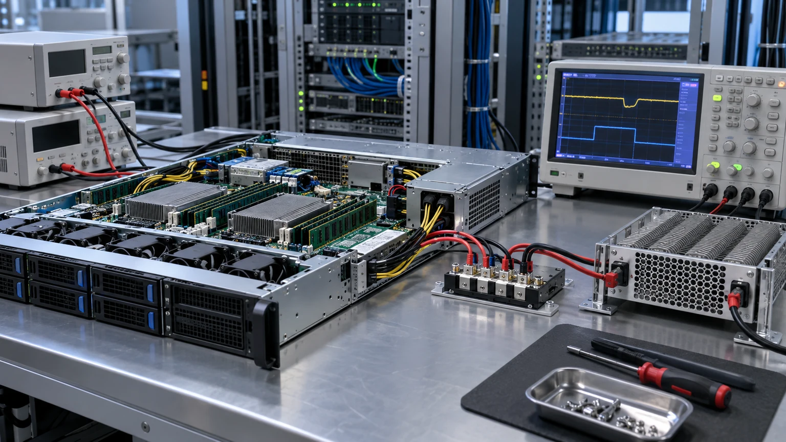
What to hand over when a 750W design is released
The final record should let another engineer or service technician recreate the decision. Include the approved PSU and host identifiers, PDB and harness revisions, input service, expected output rails, power policy, supported hardware population, relevant environmental limits, and the measurement locations used in qualification. Attach the results for sustained load, startup, and any authorized fault-state test. Note the operating condition under which each result was obtained.
For sourcing, define an approved replacement by exact compatibility evidence rather than “750W 12V” alone. A new module can share those headline numbers yet differ in connector, management response, airflow direction, input range, standby behavior, or thermal limits. A substitute should go through the same host-specific review before it reaches the spare shelf.
If the investigation finds that the 12V distribution is the limiting element, state that plainly. The engineering remedy may involve a connector, board, harness, cooling path, or system policy, depending on the finding. The value of the 750W label is that it starts a capacity discussion; the voltage and temperature delivered at the real load decide whether the assembly can use that capacity responsibly.