An industrial power supply can be rated for a warm environment and still overheat inside a control cabinet. The relevant temperature is the air reaching its inlet during sustained operation, not the weather outside the enclosure or a sensor mounted near the door. Industrial power supply thermal requirements therefore connect three things: the exact model’s output-versus-temperature rating, the cabinet’s ability to remove heat, and the way the supply is mounted among other heat-producing equipment. A cabinet that satisfies one of those conditions but not the others may lose available output or shut down when the line is busiest.
The temperature at the supply is not the room temperature
A factory may specify a maximum room temperature and assume every component in the panel sees it. In a ventilated cabinet, air passes through filters, over drives and contactors, and around cable ducts before it reaches the power supply. In a sealed cabinet, heat accumulates until the enclosure walls transfer it to the room. The supply can therefore ingest air appreciably warmer than the surrounding space, particularly high in the cabinet or downstream of another device’s exhaust.
The placement of a temperature probe changes the answer. A sensor attached to the metal case measures a surface influenced by internal heat and conduction through the mounting rail. A probe beside the cabinet door may measure relatively cool air that never reaches the converter. To characterize the operating environment, position the probe in free air near the supply’s specified intake, without blocking a vent or touching metal. If the product uses convection rather than a fan, the relevant local air path and measurement point differ; use the manufacturer’s installation drawing rather than assuming the inlet is on the front face.
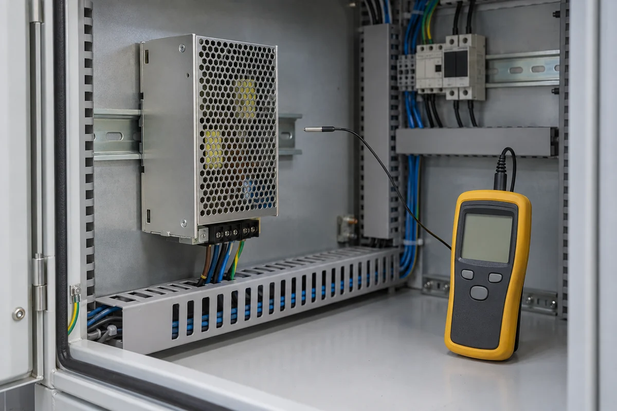
That distinction matters most after the panel has reached a stable thermal state. A cold-start reading can look comfortable even though cabinet temperature rises for hours under a steady machine load. A daytime ambient peak may coincide with maximum converter output and the heat from drives, braking resistors, network switches, and other equipment. Those coincident conditions, not the most favorable individual reading, define the credible thermal demand.
Heat inside a cabinet comes from conversion loss and neighboring loads
A supply does not turn every watt drawn from the line into useful DC output. The difference becomes heat that the cabinet must ultimately reject. For an illustrative supply delivering 240 W at an assumed efficiency of 90% at that operating point, input power is about 267 W and the supply releases about 27 W of heat. This is arithmetic, not a specification for any Powernexu product. Efficiency varies with model, load, input conditions, and temperature, so a cabinet heat estimate should use the relevant manufacturer data where it exists.
The other components may dominate. A motor drive, controller, communication equipment, and power distribution devices each add loss. A machine designer who accounts only for the PSU’s output rating can miss the point: 240 W delivered to loads is not itself 240 W of heat produced by the PSU, but some of those loads may release their own power as heat inside the same enclosure. The location of each source matters as much as its total dissipation when there are stagnant zones.
A sealed cabinet has a finite heat-transfer path through its walls. Its internal air temperature rises until wall losses and any active cooling balance the installed heat generation. Outdoor solar loading can add another heat input; a warm wall or a cabinet mounted against another hot surface reduces the temperature difference available for heat rejection. Without enclosure-specific thermal data, a fixed rule such as “leave a certain percentage of PSU capacity unused” cannot predict the final inlet temperature.
The engineer can instead separate two questions. First, what is the credible simultaneous heat release inside this specific enclosure? Second, what local air temperature does the enclosure design create at the PSU under that heat load and the highest relevant room or outdoor condition? The supply’s allowable output can then be read at that local temperature. Reversing the order—choosing a supply from its headline wattage and discovering the cabinet temperature later—can leave no comfortable operating margin.
A derating curve is an operating boundary, not a generic warning
Many industrial supplies state full output over one part of the ambient range and reduced permissible output above it. The curve may be continuous, stepped, or dependent on a defined airflow condition. Some datasheets give separate plots or notes for different mounting positions. The point is not merely that heat is bad; the curve tells the designer how much current the model may continuously deliver under the specified thermal conditions.
Read the axes and footnotes before using the curve. Is the horizontal value surrounding air temperature, inlet air temperature, or another manufacturer-defined ambient? Is the vertical value output power, output current, or a percentage of rated load? Does the plotted line presume a particular input voltage, forced airflow, spacing, or mounting orientation? A percentage curve can be applied to the wrong baseline if those conditions are ignored. A converter rated for full power in one configuration need not offer the same envelope after it is turned sideways or enclosed behind a tight door.
Manufacturer thermal guidance is deliberately product-specific. For example, Bel’s power-supply thermal design paper discusses the interaction of temperature, airflow, physical form, and orientation in derating. That supports reading the model’s published condition rather than assigning one industry-wide temperature limit to all DIN-rail and enclosed supplies. A published limit is still not a promise that a particular cabinet will provide the assumed air conditions.
Suppose a machine requires 220 W continuously and a candidate unit is labeled 240 W. Those two numbers alone do not settle the issue. If its actual installation condition permits only 80% of nominal output at the measured local air temperature, the allowable continuous output would be 192 W under that hypothetical curve. The arithmetic reveals a shortfall; it does not establish that any real model has an 80% point at any particular temperature. The remedy might be a different supply, a cooler installation position, or an enclosure change, depending on the actual curves and available space.
Peak loads deserve separate treatment. A short solenoid or motor-start pulse may be covered by a model’s documented overload capability, while the baseline output must remain within its continuous thermal rating. Conversely, repeated pulses can increase average heating and create a different thermal condition than a single pulse. Do not assume an overload graph substitutes for the continuous derating graph, or that a protection trip temperature is an acceptable normal operating point.
Mounting orientation changes the air path through the converter
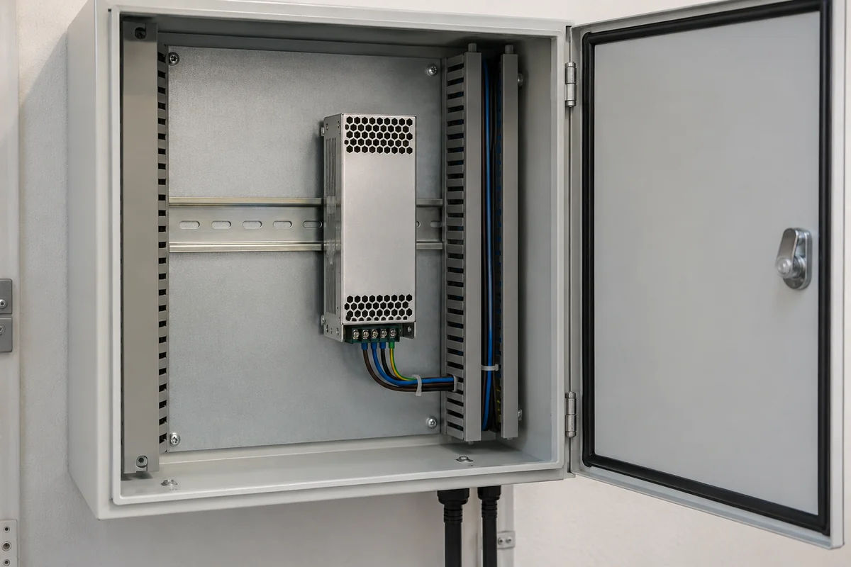
DIN-rail installation makes it easy to rotate a component until it fits between cable ducts. That mechanical convenience can change cooling. A convection-cooled supply normally depends on a vertical path in which warm air rises from its case and cooler air can enter below. Rotating the body, packing several supplies flush together, or placing a horizontal duct immediately over its vents can reduce that buoyant flow. A fan-cooled model has a different dependency: its intake and exhaust must not recirculate into each other or discharge straight into a solid panel.
Clearance dimensions are therefore functional, not aesthetic. A manufacturer may specify free space above, below, and beside a supply, and may publish reduced output for other mounting orientations. The installer needs the exact drawing for the selected unit. Borrowing spacing from a visually similar supply is unsafe because internal heat sinks, vent geometry, component placement, and fan direction can differ even when the external housings look alike.
Orientation also interacts with wiring. A dense bundle over the top vent can function like a lid. Cables pulled tightly across a fan inlet can produce an uneven flow field and complicate service. Routing conductors away from the specified cooling openings is a layout decision that should happen before the cabinet is fully populated, when ducts and terminal blocks can still move. It often costs less than adding cooling hardware to a compromised layout.
Ventilated and sealed enclosures present different thermal problems
A ventilated enclosure exchanges internal air with its surroundings. Filters, louvers, and fans can lower internal temperature, but dirty filters and blocked vents change the actual airflow over time. The incoming air may also carry dust, oil mist, or moisture that the equipment and enclosure were meant to avoid. Thus the thermal benefit must be considered together with the environmental protection required by the application, not treated as free cooling.
A sealed enclosure protects its contents from that exchange but leaves heat to cross a wall or a dedicated heat exchanger. A fan inside a sealed cabinet can reduce hot spots by mixing air, yet it does not, by itself, remove the cabinet’s total heat to the outside. This is a common source of false confidence: air feels active, but the whole panel climbs in temperature. Air conditioners, air-to-air exchangers, or a larger enclosure may be needed when the wall heat-transfer capacity is insufficient; their suitability depends on the enclosure and site conditions.
Component placement determines whether a sealed cabinet’s limited temperature headroom is spent evenly. If a drive exhausts directly toward a supply’s intake, the supply receives a higher local temperature than a bulk cabinet sensor reports. Moving the supply away from that plume or using a barrier can help without changing its electrical rating. In another layout, the supply itself may be the heat source threatening a nearby controller. There is no universal “coolest corner” independent of the installed equipment and natural or forced flow direction.
Input conditions and loading can shift the loss inside the same PSU
Output loading is the obvious variable, but it is not the only one affecting heat. Conversion efficiency can change with input voltage and output level. A supply operating near its maximum continuous output may reject more heat than it does at a moderate load, and a voltage configuration may have its own rated-output condition. Exact relationships are model-specific; use the datasheet rather than assuming the best efficiency point persists across the entire working range.
Industrial control loads often vary across a machine cycle. Controller and network loads may remain steady while actuators, valves, sensors, and interface electronics draw intermittent current. A thermal estimate based on the highest instantaneous current can overstate continuous cabinet heating; one based only on the idle state can understate it. The relevant continuous output is the portion sustained long enough to shape the supply and cabinet temperature. Peaks still need to satisfy the electrical overload and voltage-hold requirements, but they are a different calculation.
What the completed cabinet can actually sustain
The most useful result is not a universal cabinet temperature number. It is a defensible operating envelope for this supply in this installed position: local inlet temperature when the system is thermally settled, continuous output needed at that condition, manufacturer-permitted output for that orientation and airflow, and the cabinet conditions under which those observations remain valid. If a filter clogs, a cooling fan stops, or sunlight strikes the enclosure, one or more inputs to that envelope change.
That envelope can be improved in several physically different ways. Reducing unnecessary heat within the panel tackles the source. Moving the supply away from a drive exhaust tackles a local plume. Increasing clear space around its cooling path addresses a restriction. A more efficient model lowers its own loss under the relevant operating point, while a higher-rated model may offer more thermal headroom if its specific derating curve supports it. Cabinet cooling addresses the surrounding air. These measures are not interchangeable, and the best one depends on which part of the installed heat path is actually limiting the converter.