G1395-3500WNA is a 3500 W class CRPS module associated with a high-current 54 V power bus. The first issue for a buyer is identification: Powernexu’s catalog describes a 185 mm, 54.5 V unit, while Gospower’s public G1395-3500WNAA T265H page describes a 265 mm, +54 V family. Those differences affect both bay fit and downstream electronics. Treat the listing as a lead, not a released interchangeability specification. Before selecting this module for a server, PoE chassis, or power shelf, obtain the exact suffix and revision on the physical label and its controlled drawing. This article explains the electrical and mechanical consequences of that discrepancy and the operating questions a 3.5 kW, 54 V design raises.
Start with the G1395 identity, not the wattage label
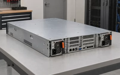
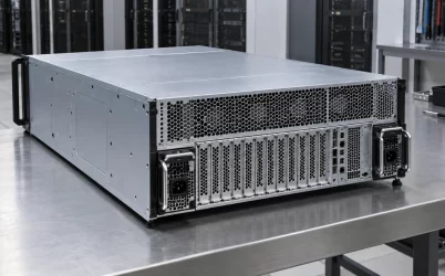
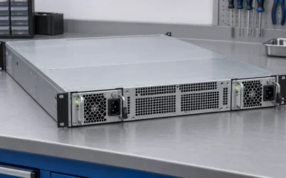
The visible manufacturer evidence is unusually important here. Gospower places G1395-3500WNAA in its T265H Titanium 54 V CRPS series and lists a 265 × 73.5 × 40 mm envelope, 90–264 Vac input, and +54 V output. Powernexu’s G1395-3500WNA product page instead reports 185 × 73.5 × 40 mm and 54.5 V, with a maximum output current of 64.22 A. Multiplying 54.5 V by 64.22 A gives approximately 3500 W, so the catalog table is internally coherent. Coherence does not establish that the two suffixes identify the same mechanical or electrical revision.
The 80 mm length difference cannot be dismissed as rounding. A 265 mm module cannot be assumed to engage correctly in a bay intended for a 185 mm module; a shorter module cannot be assumed to reach the host connector in a longer carrier. Nor does a shared 73.5 × 40 mm cross section establish matching insertion rails, latch location, rear panel, or blind-mate contact geometry. A procurement record should retain the complete part number, suffix, revision, and photograph of the rated label rather than reducing the item to “G1395 3500 W.”
The manufacturer’s G1395-3500WNAA T265H page supplies credible family context, yet it is not a published pinout or revision-controlled datasheet for every G1395-3500WNA shipment. It also describes fan reversal and a stated surge capability for the T265H series. Those statements should be mapped to the exact ordered module and its host before they become installation requirements. In particular, a web page’s “Titanium” description does not establish the exact efficiency curve, certification record, or test conditions for a specific serial number.
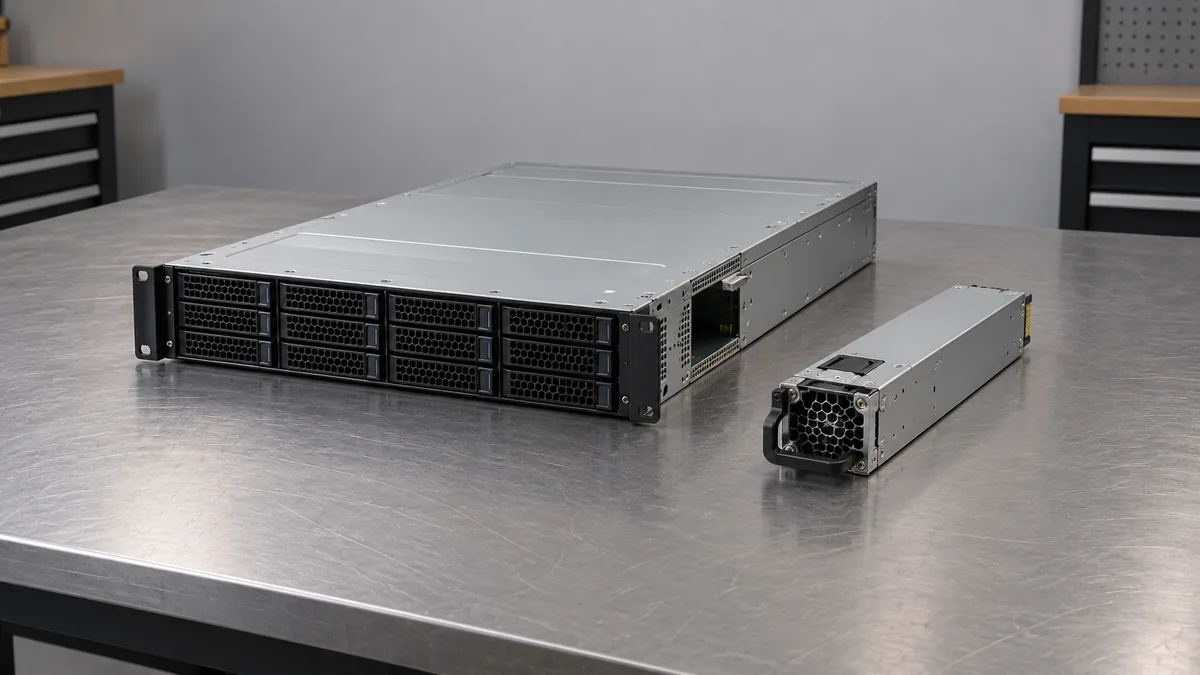
The most efficient way to settle the discrepancy is to compare four pieces of evidence for the same hardware: the label on the offered unit, the manufacturer’s drawing, the mating backplane drawing, and the seller’s listing. The physical sample and manufacturer documentation should agree on depth, output rail, rated input, and suffix. If a quotation silently substitutes WNAA for WNA, request an explicit cross-reference from the manufacturer. Similar names are useful for search, but they are not evidence of drop-in compatibility.
What a 54 V, 3.5 kW bus asks of the load side
At a nominal 54 V, 3500 W corresponds to about 64.8 A. At the 54.5 V in Powernexu’s table, the listed 64.22 A similarly corresponds to about 3.5 kW. These are arithmetic relationships between advertised voltage, current, and power; neither number independently confirms the available current across every input and temperature condition. The 54 V class should be understood as a distribution voltage, not a direct replacement for a 12 V CRPS output.
In an accelerator server, the module can feed a 54 V distribution board, which then supplies local converters for the voltages required by the processor, accelerator, memory, and auxiliary loads. The intermediate bus reduces current for a given transported power compared with 12 V: 3500 W divided by 12 V is approximately 292 A, whereas the same power at 54 V is about 65 A. This comparison says why higher-voltage distribution is attractive. It does not imply that a 54 V module may be plugged into a 12 V host, or that every converter is rated for every possible 54 V bus tolerance.
For a PoE or network-power application, the system architecture may be different. The G1395 can be a candidate for a shared DC bus feeding switching equipment or port power stages, but a PoE port’s classification, isolation, control, and output voltage are determined by the downstream power sourcing equipment. A 54 V PSU by itself is not a complete PoE power source and should not be described as directly suitable for a port without the intervening circuitry. The article’s Powernexu product listing identifies the offered module; the host design still determines its use.
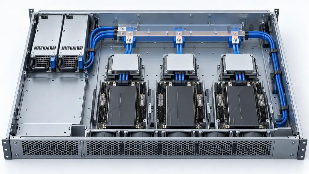
Bus current should be budgeted at the input of each downstream converter. Suppose a hypothetical design has three converter branches drawing 900 W, 850 W, and 700 W from the bus, plus 150 W of other 54 V demand. The aggregate is 2600 W, or roughly 48.1 A at 54 V. That figure leaves a numerical gap to 3500 W, but it says nothing about the manufacturer’s input-dependent rating, peak load excursions, ambient temperature, sharing behavior, or connector temperature. Its role is to reveal which branches and conductors carry the current, not to certify the system.
Large branch loads also make distribution resistance visible. At 65 A, even 10 milliohms of combined path resistance would dissipate about 42 W by I squared R. That resistance is an illustrative system assumption, not a G1395 measurement. Contacts, busbars, wiring, and board copper each contribute to the actual path. A warm connector can signal excessive contact resistance even when the PSU’s own telemetry indicates an acceptable output current. The distribution design therefore needs its own ratings and thermal evidence.
Input range does not define full-power availability
Gospower’s T265H page states 90–264 Vac input. It does not, in the public text examined here, provide a condition-by-condition output-power table for the G1395-3500WNA suffix. A broad acceptance range states where the unit can operate under specified conditions; it does not establish that 3500 W is available at 90 Vac. High-output server PSUs commonly face input-current and thermal constraints at lower line voltage, so the exact power-versus-input table is a necessary document for a full-load deployment.
Consider two racks that use visually identical servers. One has a suitable high-line feed; the other is supplied from a lower-voltage circuit. The same module may present different usable output ceilings if its controlled rating specifies input-dependent operation. The engineering issue is not merely whether the plug fits the receptacle. Branch-circuit current, rack PDU rating, cord and connector rating, the number of modules on the feed, and the manufacturer’s permitted AC range under the expected load all affect deployment.
AC input power is also higher than delivered DC power because conversion has losses. For illustration only, a 3500 W DC load at an assumed 95% efficiency would draw about 3684 W from AC, before considering any system loads outside that PSU. At an assumed 230 V and power factor of one, the simple current quotient is about 16 A. Real input current depends on measured power factor, input voltage, efficiency at that point, and waveform; this example is not a branch-circuit sizing instruction or a claimed G1395 test result. It shows why a 3.5 kW module can be a significant facility load even before multiple modules are installed.
The 265 mm question reaches beyond the PSU bay
If the offered unit is the 265 mm T265H variant, the extra depth occupies space that may already belong to fans, a midplane, a power distribution board, cable bends, or accelerator airflow hardware. A bay can appear wide and tall enough from its rear opening yet fail because the internal stop or blind-mate connector lies in the wrong plane. The insertion travel also changes the location of the AC inlet, latch, fan intake or exhaust, and service handle relative to a populated rack.
Mechanical interchangeability also depends on the connector and guide system. The host may rely on sequencing contacts, precharge behavior, signal pins, presence detection, and latching geometry. Those details are not recoverable from a broad CRPS label or a product photo. A drawing should identify the mating connector and its tolerances, while the host owner should approve the module’s insertion behavior. If the seller provides only overall dimensions, the part is still a candidate, not an approved replacement.
This is the point at which the Powernexu and manufacturer listings must be reconciled, rather than averaged. A 185 mm dimension and a 265 mm dimension describe materially different packaging. There may be a catalog error, a separate mechanical variant, or an unexplained suffix difference; the currently available public pages do not settle which explanation applies. Publishing one figure as universally true would hide the very risk that matters most to a buyer.
Redundant operation changes the meaning of 3500 W
Two 3500 W modules in a redundant chassis are often intended to maintain operation after one module is lost. In such a 1+1 arrangement, the surviving module must carry the whole critical load within its actual allowed rating at the available AC input, ambient temperature, and airflow. The modules’ nameplate powers should not be added to describe failure-survivable capacity. A different architecture can deliberately combine capacity, but then the loss of a module changes the available power and may require load shedding.
Current sharing is a separate interface question. Modules that both produce a nominal 54 V output will not necessarily share acceptably when paralleled. The distribution board needs the prescribed ORing or isolation scheme, and the supplies need compatible share control and fault behavior. An output-voltage difference of a few tenths of a volt can alter current distribution depending on the control method. The 54 V versus 54.5 V discrepancy is therefore more than cosmetic when evaluating mixed inventory. The exact allowed pairing, sense arrangement, and current-share limits must come from the relevant manufacturer and host documentation.
For example, a hypothetical server drawing 3.1 kW continuously may appear to fit under a 3.5 kW headline in a two-module chassis. If the manufacturer’s applicable low-line or elevated-temperature rating is below 3.1 kW, however, the server is not 1+1 capable under those conditions. Conversely, a design with controlled load shedding or more than two modules might remain operational under a reduced capacity. The architecture, not the printed wattage alone, defines continuity.
Where the public record stops
The public pages support a useful preliminary identity: a G1395 3500 W class, nominal 54 V CRPS product family and a Powernexu offering under the G1395-3500WNA name. They do not expose a complete revision-specific pinout, output tolerance, hold-up time, ripple limit, transient response, combined-output rating, telemetry command set, or environmental derating curve in the evidence reviewed for this article. Those values should not be copied from a neighboring G1395 or another T265H model merely because the enclosure looks alike.
For a purchase intended as a drop-in spare, the missing information is concrete: exact ordering suffix, label and revision, envelope drawing, mating interface, output set point and tolerance, AC rating at the site’s voltage, and host approval. For a new 54 V platform, the design owner additionally needs bus protection and distribution ratings, branch converter input limits, fault isolation, and the expected load profile. Those two buying situations differ. A spare must match an existing platform; a new design can choose its platform around the available module.
The most actionable interpretation of G1395-3500WNA is therefore a 3.5 kW-class candidate whose 54 V bus architecture is plausible, but whose public mechanical description is unresolved. The 80 mm depth discrepancy makes a paper interchangeability claim unsafe. Once the exact unit’s label and controlled documents agree with the host design, the 3500 W rating can be evaluated against the actual input feed, distribution losses, cooling path, and surviving-module load. Until then, the model name and public product table are a starting point for identification, not evidence that the unit fits or can sustain a particular server.