An ultra-compact open-frame power supply is useful only if the finished equipment has room for the installed assembly, not merely the bare circuit board. The PCB outline excludes cable exits, input protection, insulating barriers, mounting hardware, airflow space and the path a technician needs to assemble the product. A converter can be smaller on a catalog drawing yet demand a larger reserved zone inside an enclosure. For an embedded controller, gateway or instrument, compare the complete occupied envelope and the host’s safety and cooling arrangement before treating a miniature board as a space-saving choice.
Start with the space the equipment can actually surrender
“Ultra-compact” is a relative description, not a standard footprint class. The term may describe board length and width, component height, volume, power density or simply the absence of an outer metal case. Those are different properties. A short but wide PCB might fit a broad control cabinet and fail in a narrow edge gateway. A slender board can fit beside a processor card but leave too little room for the mains input harness. A low-profile board may slide under a cover while its connectors still obstruct the cover’s ribs. The search for a small supply becomes useful when the host equipment’s available three-dimensional space is known.
Draw the usable region, not just the empty rectangle visible in a photograph. Record the enclosure walls, lid features, nearby boards, heat sinks, mounting bosses, connector openings and any component that moves during assembly or service. Note which surfaces are conductive and which compartments can be reached without a tool. A battery, antenna cable or display hinge may claim space that looks vacant when the enclosure is open. The supply also has to remain accessible for factory fastening and wiring, even if it will not be field replaceable.
The relevant drawing has three boundaries: the converter’s physical outline, a routing and access area around it, and any electrical or thermal separation required in the finished product. These boundaries may overlap in places, but they should not be silently collapsed into one catalog dimension. Once the host reserves the actual occupied region, a purportedly smaller board can be compared fairly with an enclosed module, a different board orientation or an external adapter.
The PCB edge is not the end of the footprint
In a very small assembly, wiring can take more useful plan area than the converter. An input connector may face a wall and require its cable to bend across adjacent circuitry. Output wires may need a different exit direction to reach the load without crossing the input side. A connector drawn within the PCB outline can still need clearance for the mating plug, latch, fingers or assembly tool. Screws and standoffs also consume space around mounting holes; their heads cannot be allowed to interfere with traces or the enclosure.
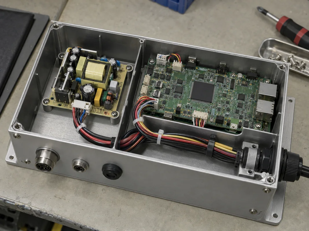
Consider an embedded device with a narrow slot beside its main board. One candidate open-frame supply has a smaller bare PCB than another. The smaller candidate puts both connectors at the narrow end facing the wall. Its installed cable loops protrude into the main board’s area. The other candidate is slightly larger on paper but places the connectors along an accessible side, so its harness stays in an existing cable channel. This is a hypothetical layout comparison, not a claim about any Powernexu model. It illustrates why a footprint comparison must include connector orientation and the physical route to the load.
Board thickness alone does not settle vertical fit, either. Component bodies, solder joints below the PCB, standoff height, wire insulation and the connector release motion all contribute to the occupied height. The separate low-profile open-frame integration discussion treats that vertical problem in depth. For an ultra-compact design, the distinctive question is how much usable enclosure space remains after the small board is mounted and connected.
A practical layout exercise is to place a full-scale board outline, connector keep-out shapes and proposed cable paths onto the host CAD model. Mark the mounting and test-access directions. If a wire exits toward an enclosure seam or a structural post, rotating the board may solve the problem without changing the converter. If rotation brings the mains region beside an accessible surface, it may create a different safety problem. Space cannot be optimized independently of the electrical boundary.
What miniaturization changes in the electrical neighborhood
Open-frame construction exposes a supply’s circuitry for integration into a protected product. Reducing the board area does not erase the need to maintain the spacing and insulation arrangement specified for that component. Fasteners, chassis metal, cables and neighboring boards can alter the environment around the input, primary-side components and isolated output. A layout that looks efficient in top view may be unsuitable when a grounded bracket sits immediately under a live region. The permitted mounting arrangement comes from the exact manufacturer’s documentation and the final equipment’s applicable safety design, not from the general phrase “open frame.”
For a small enclosure, wire routing is often the decisive variable. The input path should have an intentional route from the equipment’s inlet or power-entry assembly to the converter. The output path should reach the load without drifting into the mains-side area, rubbing on an edge or being pinched when the cover closes. Protective conductors, if required by the design, need a defined termination and mechanical retention. Treat strain relief and abrasion protection as occupied space. They are not accessories that can be added after the converter has been packed against every nearby surface.
Component marks require careful interpretation. UL Solutions explains that a Recognized Component is assessed for use within a larger end product under defined conditions of acceptability. That is relevant to compact open-frame layouts because an approved component does not automatically approve a tight new mounting cavity, enclosure material or user-access arrangement. The project team needs the actual component file, installation instructions and relevant end-product requirements before making a certification claim. A small PCB does not make the safety review proportionally small.
A smaller board can make cooling harder
Miniaturization concentrates heat sources. The enclosure must remove the converter’s losses, and the available path depends on component orientation, neighboring heat sources and actual air movement. “Convection cooled” on a product page describes a specified operating condition. It does not mean the same rating is available when the board is sealed inside a stagnant pocket beside a processor or behind a display. Nor does a system fan guarantee cooling if its flow bypasses the supply. The local air temperature at the converter may exceed the equipment’s external ambient.
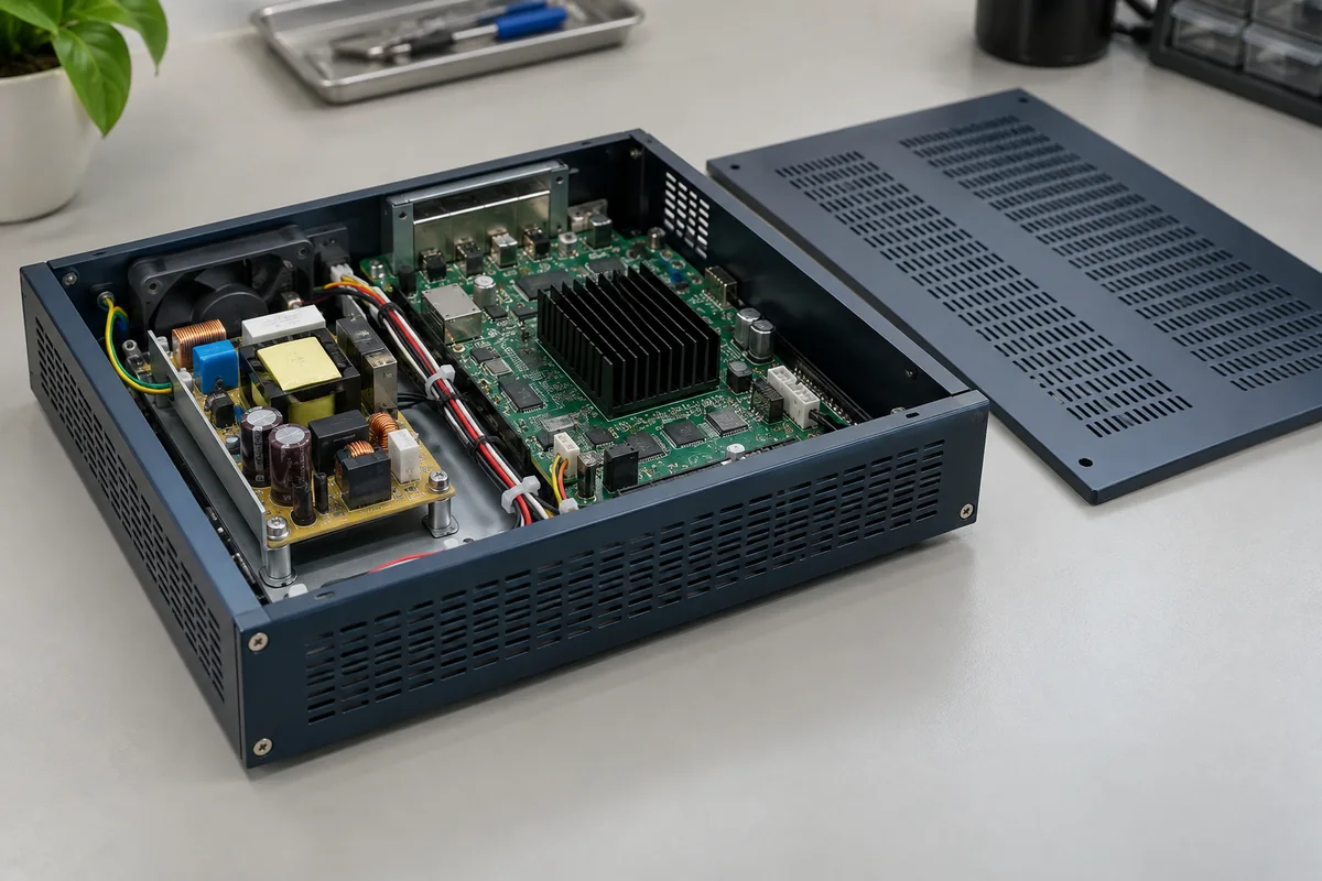
In a compact instrument, the apparent shortest cable route might put the supply behind a dense wiring bundle. That bundle can obstruct natural convection and make component temperatures less uniform. Moving the board a short distance toward a vent may improve its thermal environment, but could crowd an input connector or place a heat source near a temperature-sensitive sensor. These are equipment-layout trade-offs. The right placement comes from the host’s geometry and the exact supply’s thermal guidance, not from the intuition that a low-wattage board will always remain cool.
Compare the published output rating with its stated input and temperature conditions, the required airflow and any derating curves. A model may have one continuous rating under natural convection and another with defined forced air. Do not borrow either rating from a visually similar product. In a small enclosure, use thermal measurements at the specified locations under the machine’s realistic operating modes, including high load and warm internal ambient. If the manufacturer’s data does not describe the proposed arrangement, obtain guidance rather than inventing a safe separation or temperature limit.
Choose the packaging category before comparing millimeters
Not every compact power solution gives the host equipment the same responsibilities. An open-frame AC-DC board, an encapsulated PCB-mount converter, a housed industrial supply and an external adapter may all provide a similar output voltage while shifting insulation, touch protection, mounting and thermal work to different places. A potted module can simplify handling in one design but may have different heat-removal and repair implications. An external adapter removes mains conversion from the host enclosure, yet requires an input connector, cable management and a suitable location outside the product. It may be the genuinely smaller internal solution even when the adapter itself is physically larger.
A miniature board is therefore not automatically the best fit for every enclosure. It is compelling when the host already provides the protected cavity, a suitable power-entry route, a predictable cooling path and the manufacturing controls to install the board consistently. It is less attractive when a custom barrier, awkward harness, separate shielding, extra connector or extensive service disassembly consumes the saved space. Packaging should be compared at the finished-product level rather than by whichever catalog outline has the smallest area.
A real product page is a starting point, not a mechanical drawing
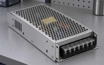
Powernexu lists the GW-TO25WV12 open-frame supply as a 25 W, 12 V option for low-power embedded and industrial equipment. That is a relevant product type for a small internal-power discussion. Its public product page does not provide a verified board outline, mounting-hole drawing or connector-envelope dimension. The page therefore cannot support a claim that this model fits any particular compact cavity. A purchaser considering it should request the controlled drawing and installation conditions for the exact variant before making a fit assertion.
As soon as a candidate is identified, compare documents that describe the same physical revision. The mechanical drawing should show board length, width, mounting-hole coordinates, maximum component height on each side and connector locations. The electrical data should describe input and output requirements, relevant protection behavior and load conditions. Installation information should state any mounting, spacing, earthing or airflow assumptions. A sales photograph can help visualize the board, but perspective and lens distortion make it a poor measuring instrument.
Where the smallest board is not the smallest assembly
Imagine a compact edge controller that accepts AC input and supplies a single 12 V electronics rail. The designer has two conceptual placements. In the first, a tiny open-frame board sits deep behind the logic assembly. This minimizes the visible PCB footprint but requires a long input run, a sharp output-cable turn and removal of the logic board to inspect the supply. In the second, a somewhat larger board sits next to the power-entry compartment. Its mounting area is greater, yet the cable runs are shorter and the input region is easier to guard. No specific product or measured performance is implied by the example.
The choice is not resolved by adding arbitrary “safety margins” to each board’s length and width. Lay out the actual connector envelopes and manufacturing sequence. Ask whether an assembler can fasten the board without contacting nearby parts, mate the connectors without forcing a cable against the cover, and close the enclosure with the intended strain relief in place. Then test the cooling arrangement under the machine’s operating states. A design that passes these concrete spatial questions can be more compact in practice even if its PCB is larger on paper.
Ultra-compact should ultimately describe the completed equipment’s efficient use of space. It should not be a promise that a bare converter will occupy only its printed-circuit-board dimensions. If the host has a suitable protected cavity and the documented converter fits with its wiring, thermal path and assembly access intact, the small open-frame form can be a strong choice. If those supporting regions consume more room than the board saves, change the placement or packaging class rather than compressing the required boundaries out of the design.