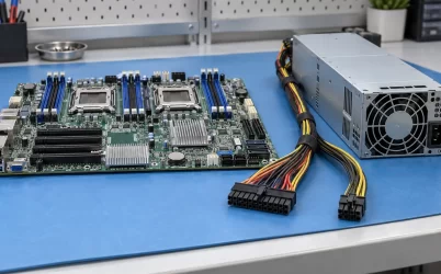
The G1666-3600WNA is listed by Powernexu as a 3600 W hot-pluggable CRPS module measuring 185 × 73.5 × 40 mm, with a 90–264 V AC input range. Its published product record describes a 12 V, 300 A output. However, public listings for the related Gospower G1666-3600W family describe a 54 V architecture, and an original manufacturer document for the exact WNA suffix was not available during this review. That difference changes the backplane, converters, protection, and service strategy. Before specifying this module, obtain the exact label and revision-controlled datasheet and resolve the output rail. This article explains the evidence needed to turn the listing into a qualified server power choice.
Resolve the output rail before designing the host
Powernexu’s G1666-3600WNA product page lists 12 V and 300 A. The arithmetic is internally consistent: 12 V multiplied by 300 A equals 3600 W. Yet a consistent calculation cannot establish that the underlying product data are correct. Public information for a G1666-3600W without the WNA suffix associates the family with a 54 V main rail. The suffix could identify a different configuration, a product revision, or a catalog transcription issue. None of those explanations can be assumed from the available public records.
This is a consequential distinction, not a minor tolerance. A nominal 12 V source at 3600 W carries approximately 300 A. A nominal 54 V source at the same power carries approximately 66.7 A. If those currents flowed through the same resistance, the 12 V path would dissipate roughly twenty times as much heat by the I²R relationship. Conversely, a 54 V bus requires downstream conversion where equipment expects 12 V. Connector assignment, insulation, switching devices, sensing thresholds, and fault coordination also change. A supply that physically slides into a bay may still be electrically incompatible.
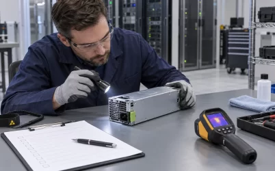
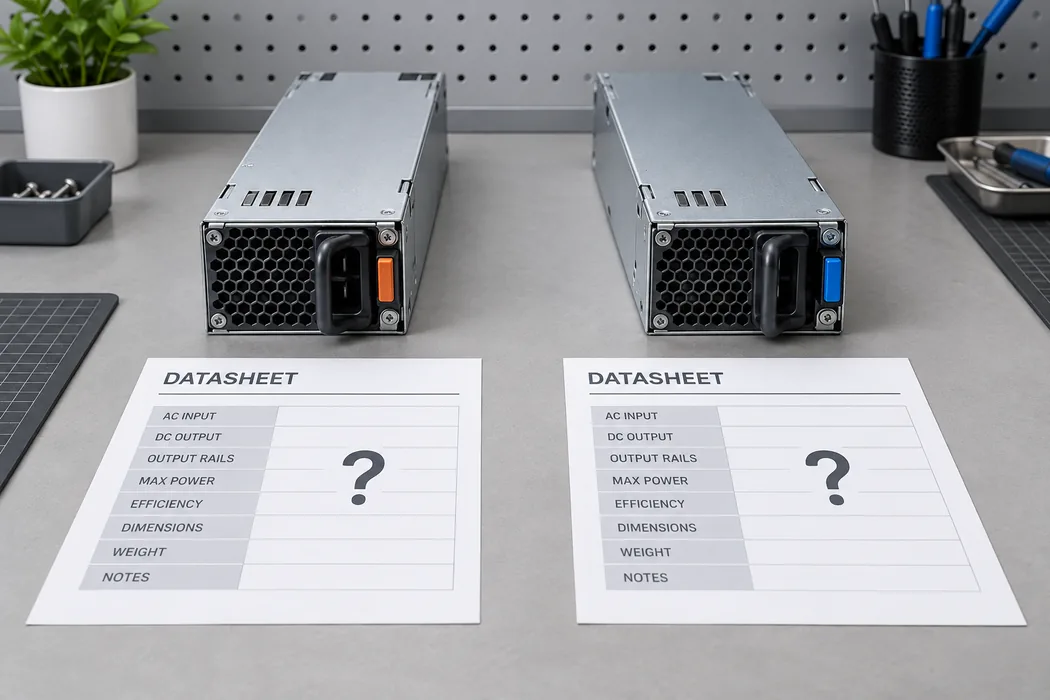
Ask the supplier for a photograph of the label on the exact stocked unit, including the complete model suffix and revision. Pair it with a manufacturer datasheet that identifies the main and standby rails, their current limits, output tolerance, allowable input conditions, and connector drawing. The backplane drawing should identify contact positions and control pins for that same revision. A bench measurement can confirm the observed rail on one sample, but it cannot replace documentation for production sourcing or guarantee that future lots are identical.
Separate nameplate capacity from available operating capacity
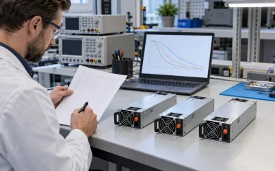
The site record gives a 3600 W maximum output and a 90–264 V AC input range. It does not present a power-versus-input curve for this specific suffix. The lower end of an accepted AC input range may support less output than the upper end. Temperature, airflow, altitude, and redundant operating mode can introduce further limits. Accordingly, do not promise 3600 W at every voltage in the listed range until the exact manufacturer’s rating table says so.
Start with the site power conditions rather than a nominal utility label. Record the voltage at the server inlet during the expected worst operating period, including any transfer to an alternate feed. Then compare the load envelope with the module’s continuous rating at that input. A system intended for operation across multiple regions needs an explicit capacity statement for each supported feed class. If a fallback feed reduces capacity, the platform may need a workload cap or additional supply modules. The acceptance criterion should identify the input voltage and thermal condition under which the advertised server power is available.
The AC side also requires its own calculation. Output power is not equal to input power because conversion produces losses. The branch circuit, PDU outlet, power cord, and inlet must be evaluated using the exact unit’s rated input current and approved protection requirements. An estimate based on 3600 W divided by a wall voltage can miss efficiency, power factor, inrush, and low-line behavior. Use the manufacturer input data and the intended rack distribution equipment to avoid moving an overload from the DC side to the AC feed.
If 3600 W is a peak or conditional rating rather than a continuous rating for the proposed site, the system bill of materials must state that condition. Procurement descriptions often compress these qualifications into a single wattage figure; the engineering release should not. Record the evidence document and revision beside the approved operating envelope so replacements can be checked against the same baseline.
Choose the distribution architecture after the rail is known
With a verified 12 V variant, the host must manage very high current immediately after the module’s edge interface. Contact resistance, copper geometry, busbar joints, protection devices, and return paths can dominate the local loss and temperature rise. The 300 A listing provides an order of magnitude for planning, not a license to assign 300 A to a particular connector or board. The actual contact map and current-sharing arrangement must come from the exact mating specification.
A verified 54 V variant shifts the problem. Current on the main bus is lower for the same power, but local DC-DC stages must create the rails used by processors, accelerators, fans, storage, and management circuitry. That architecture can simplify the high-power trunk while adding converter placement, conversion loss, control sequencing, and protection boundaries near loads. It can be suitable for an accelerator tray or distributed compute fabric when the platform was designed for the higher-voltage bus. It is not an interchangeable spare for a 12 V backplane merely because its envelope is similar.
For either rail, trace the energy path from the PSU contacts to every significant load. Identify each branch’s sustained demand, transient demand, protection element, connector, and voltage measurement point. Shared copper near the source carries combined current; a branch after the split carries only its local load. A practical drawing includes both the outgoing conductor and the return. An overlooked return bottleneck can produce voltage drop and heat even when the positive path appears generous.
Consider a hypothetical 0.5 milliohm path carrying 300 A. Its loss would be 45 W and its drop 0.15 V. Those are illustrative calculations, not measurements or specified limits for this model. The same resistance at 66.7 A would dissipate about 2.2 W, illustrating why the output-rail question matters so much. The actual permissible drop follows from the downstream equipment’s input limits, while the thermal limit follows from the connector, board, and chassis design. Measure both under the intended load rather than adopting the example as a design target.
Define redundancy as a failure state, not a module count
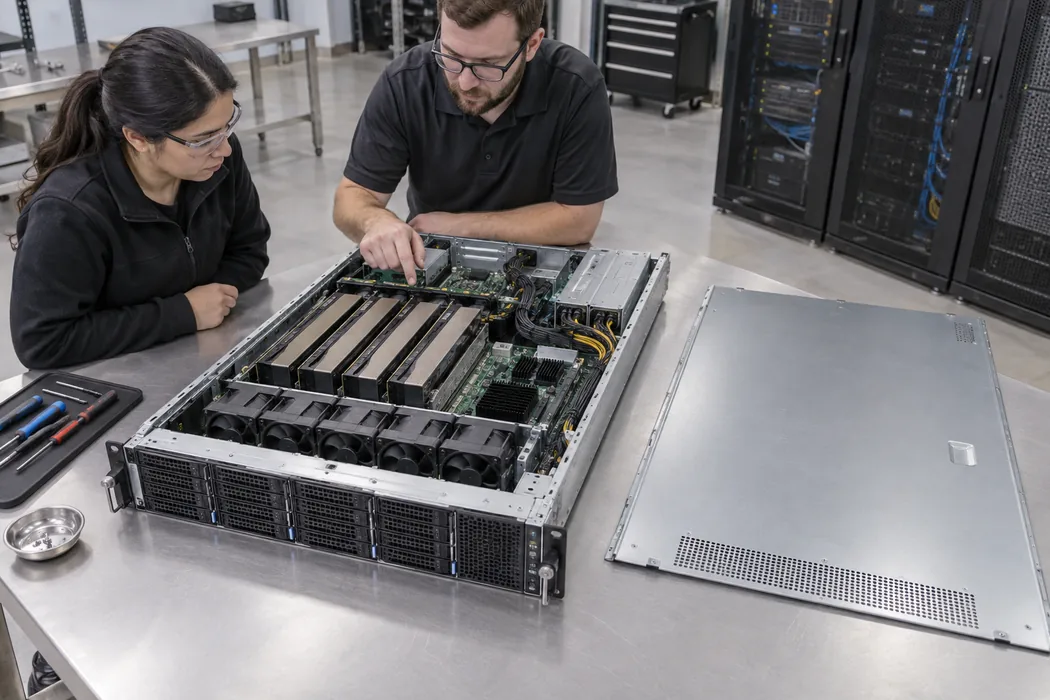
Hot-pluggable describes a service feature, but it does not prove that any particular server can remove one module without interrupting operation. The backplane must support safe insertion and extraction, the control signals must be compatible, and the remaining installed modules must carry the load under the relevant input and temperature conditions. If a server uses two modules in a one-for-one redundant arrangement, its usable protected capacity is limited by what one module can supply after the other is lost. Adding their nameplates would describe installed capacity, not one-failure capacity.
For a larger parallel set, build a table of the installed module count, available module count after the intended failure, and per-module load in each state. Include the possibility that a feed failure removes more than one module when multiple supplies share a PDU or upstream breaker. The difference between module redundancy and feed redundancy becomes visible only when the complete AC-to-load path is drawn. The desired failure tolerance should be explicit before choosing a PSU quantity.
Parallel behavior also depends on current sharing and fault isolation. Without the exact WNA datasheet, it is unsafe to assert a specific ORing device, share protocol, or supported parallel count. Request the manufacturer’s integration note and verify the backplane’s control scheme. During qualification, observe output stability and per-module current when one unit is inserted, removed, or faulted at representative load. A successful steady-state run with all modules present does not establish a safe single-failure transition.
Service procedure matters at this power level. The replacement unit should match the approved suffix, revision policy, airflow direction, and firmware or management compatibility requirements. A physically identical module with another output architecture could create a hazardous mismatch. Define how technicians identify the correct spare before opening the rack, and retain the label evidence in the approved parts record.
Make the thermal test match the actual chassis
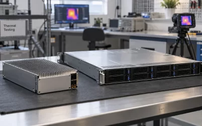
A 185 × 73.5 × 40 mm enclosure is compact for a 3600 W class supply. The dimensional match is necessary for a candidate bay, but it says little about cooling performance in a populated server. Fan direction, inlet obstruction, neighboring module exhaust, cable routing, and backpressure can change the air available to the PSU. Obtain the exact unit’s airflow direction and intake-temperature limit. A similar-looking family member may have a different fan configuration.
Measure the system in its most demanding sustained state and after thermal stabilization. Useful locations include the PSU intake, PSU exhaust, edge connector region, distribution board, protection devices, and downstream converters. A converter can be within its own limit while a contact or copper neck overheats. Likewise, an acceptable PSU exhaust reading cannot establish that the adjacent PDB is cool. Instrumentation should follow the anticipated heat sources rather than a single convenient temperature sensor.
Workload matters as much as ambient air. Accelerator servers can change load quickly, and the resulting current step can reveal a distribution or converter problem that a smooth electronic load misses. Use a test profile reflecting the intended CPU, GPU, fan, and memory activity, while separately checking steady maximum load. Capture voltage at the load as well as at the module output; a healthy source reading can coexist with excessive drop downstream.
The test record should state the inlet voltage, ambient conditions, fan state, number of active supplies, load profile, and acceptance limits. Repeat the critical points after a module is removed if redundancy is claimed. If the platform cannot remain within its electrical and thermal limits during that state, the protected capacity must be reduced or the architecture changed.
Turn uncertain catalog data into a controlled purchase decision
The first purchase gate is identity. Match the supplier quote, product label, manufacturer datasheet, and incoming-inspection record to the full G1666-3600WNA designation. Do not shorten it to G1666-3600W in an engineering drawing, because the public information attached to that shorter designation points to a different main-output architecture. Ask the manufacturer or authorized supplier to explain the suffix and provide a revision history if the output rail changed.
The second gate is electrical fit. Confirm input type, main and standby outputs, pin assignment, startup sequence, remote enable, status signals, and any management interface using model-specific documents. Verify the host’s connector mating and control compatibility on the actual board revision. A datasheet for another unit in the same mechanical series can guide questions, but it should not be substituted for the exact model’s drawing.
The third gate is system performance. Document available power at each supported input condition, protected capacity after the intended failure, thermal margins in the installed bay, and voltage at the farthest critical load. Record test samples by serial number and revision. If a vendor proposes an alternate module, run the same checklist rather than assuming that wattage and dimensions establish equivalence.
Once these gates are met, the compact 3600 W module can be considered for a high-density compute platform whose electrical architecture matches the confirmed output. Until then, the open 12 V versus 54 V discrepancy is a hold point for integration and procurement, not a detail to resolve after hardware arrives. A clear evidence package prevents a wrong-rail purchase, protects the backplane design, and gives operations a reliable replacement specification.