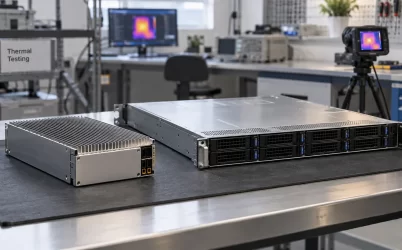
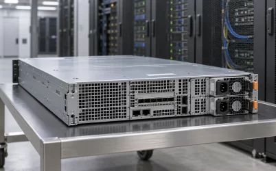
A server power supply’s 24-pin and 8-pin connectors usually serve different board inputs. On an ATX- or SSI-style server board, the 24-pin connector commonly carries the main motherboard power and control signals, while an 8-pin 12 V connector feeds a CPU power stage. Some boards require two 8-pin inputs; others use a proprietary backplane or different pin count altogether. The safe answer is not to match pins by appearance but to identify the exact board’s power-connector definitions and supported PSU harness.
The phrase “server power supply 24 pin 8 pin” often appears when someone is replacing a supply, wiring a bare server board, or wondering why the server will not start despite a connected 24-pin cable. The distinction matters because physical fit is not a complete electrical specification. Connector families, keying, rail assignment, wire gauge, control signals and host requirements must agree. Never plug an 8-pin cable into a socket merely because its shell seems to fit.
The 24-pin connection is the board’s main power interface
In conventional ATX-derived designs, the 24-pin motherboard connector carries several supply and control functions. It can include main voltage rails, grounds, standby power and signals used to request or report power state. The exact allocation belongs to the applicable standard and the board’s documented interface. The point for a server integrator is functional: the board may need standby power before it can accept a front-panel power request, and it may need a power-good indication before allowing normal startup. Connecting only the high-current CPU feed does not replace those functions.
A 24-pin socket on a server board does not prove that any consumer ATX supply is a supported choice. The system may impose power capacity, redundancy, thermal, cable, management or mechanical requirements beyond the familiar connector. It might have an adapter or power distribution board between removable modules and the motherboard. In that architecture, the connector visible on the board is only one interface in a larger controlled assembly.
When a board does not start, the 24-pin cable is tempting to treat as a simple on/off plug. Yet standby power, front-panel logic, management firmware and protection state all affect the sequence. A server with fans or management LEDs active is not necessarily receiving the main power required by its processors. Conversely, a dark front panel may reflect missing standby power, a host-board issue or a deliberate inhibit state. Connector count alone does not diagnose it.
An 8-pin CPU input is not another copy of the 24-pin plug
An EPS-style 8-pin 12 V connector typically delivers substantial 12 V current to voltage-regulator circuitry near a processor. The board converts that rail into the much lower voltages its CPU requires. The connector is therefore associated with a concentrated load and must have the correct mating cable, pin assignment and conductor capacity. A second socket may support another CPU, add current capacity, or serve another documented load path; do not infer its purpose solely from location.
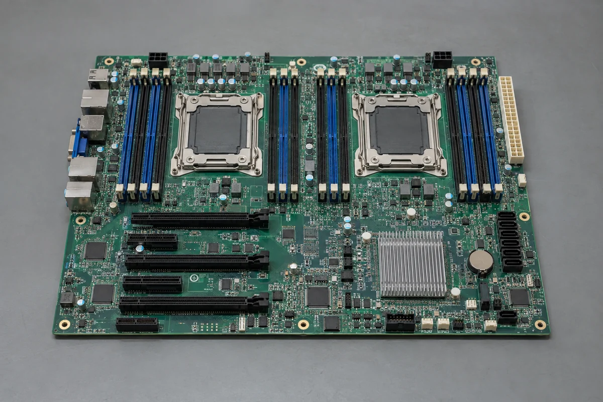
Official server manuals show why exact identification matters. A Supermicro storage-server manual, for example, describes a platform where 8-pin 12 V inputs can be used with or, under its documented conditions, as the sole 12 V inputs. That is a statement about this named board, not a universal rule that 24-pin can always be omitted. The correct manual can also specify whether both 8-pin sockets are mandatory in a dual-CPU configuration.
An 8-pin PCIe or GPU power cable must not be assumed interchangeable with an 8-pin CPU cable. Some shells look similar but are keyed and wired for different assignments. Modular PSU-side connectors create a further trap: two detachable cables may fit the PSU’s chassis socket while using different pin maps between brands or models. Never reuse modular cables across unrelated supplies on appearance alone. Use the exact manufacturer-approved harness and board documentation; if the cable’s identity is uncertain, do not energize the assembly.
The warning is not merely theoretical. A wrong cable can place a voltage on a ground contact or a signal pin, with immediate damage potential. A cable that happens not to damage hardware can still lack the current capacity or correct sense path for sustained load. For a hot-swap server, attempting to create an adapter from a removable PSU’s edge connector to a 24-pin or 8-pin motherboard socket adds another whole set of enable, standby and protection questions that a passive wire mapping does not answer.
What two 8-pin sockets actually mean on a dual-socket board
Many dual-processor server boards provide more than one 8-pin 12 V input because CPU current demand and trace distribution are substantial. It is common for the connectors to be placed near separate processor power stages, but the host manual determines the supported population and startup behavior. Some boards require all specified feeds for operation. Others may support limited configurations with one connector and one processor. Treat a possible reduced configuration as a named platform behavior, not a general workaround.
Even if a board starts with one cable absent, booting is not proof that the wiring is adequate under load. A processor can draw much more during sustained work or a transient than it does while idling in firmware setup. An undersupplied path may cause voltage sag, connector heating, shutdown, throttling or intermittent errors. The useful evidence includes the host connector specification, approved PSU and cable set, supported CPU configuration, and rated current through the complete path.
A simple visual inventory helps explain many mistaken installations: count the board’s power inputs and identify their exact labels from the board silkscreen and manual; count the separate PSU harness connectors; then determine which cable mates to which board input. That is not a generic pinout test. A printed “CPU_PWR” label or manufacturer’s connector table carries more weight than a reseller listing that says only “24+8 pin server PSU.” Where the system has a PDB, include its cables and connectors in the path.
Do not confuse connector shape with a PSU output architecture
A server PSU may produce one dominant 12 V output and a standby rail, while the host PDB or motherboard converts that power into the voltages needed elsewhere. Another system may use a multi-output supply with a more ATX-like harness. Both could eventually feed a board that presents 24-pin and 8-pin sockets, but their module-side wiring and control are not equivalent. The motherboard connector says what arrives at that boundary, not how the removable PSU is built internally.
This distinction becomes especially visible in redundant servers. Two hot-swap modules may slide into a cage and feed a PDB. The PDB then distributes protected output to motherboard inputs. Replacing a module requires matching the cage, blind-mate connector, output, control and host approval; the presence of a 24-pin plug somewhere downstream does not make any ATX PSU a direct substitute. Likewise, a desktop 24-pin PSU with adequate labeled watts is not automatically able to share current or survive the failure state expected of a 1+1 server.
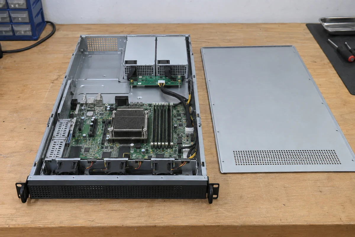
For a nonredundant rack workstation with a cabled supply, the 24-pin and 8-pin harness may be directly relevant to purchasing. For a CRPS-style host, the same phrase may describe cables on a distribution board rather than the removable module. Identifying which architecture is in front of you prevents the familiar error of shopping for a PSU by board-side connector while ignoring the bay-side interface.
Reading the board manual before attaching power
The most useful diagram is the exact host-board connector page, not a generic internet pinout. It should identify connector names, locations, supported supply type and any required additional power inputs. A system service guide can show how the PSU, PDB and harness fit together. Manufacturer documents may also define whether a high-current 8-pin connector is mandatory for a particular processor or expansion configuration. If the manual is incomplete, obtain the controlled board or system information rather than trying alternate cables until one boots.
Inspect the power supply’s own documentation at the same time. Confirm whether its 24-pin and 8-pin cables are permanently attached or modular, which sockets on the PSU they belong to, and whether the exact cable set is approved for the model. A listing that claims “8-pin CPU” is not enough if the photographed cable is ambiguous. Cable extensions and adapters add contacts and resistance; they should not be introduced merely to make an unsupported installation appear to fit.
Electrical capacity is separate from connector count. A supply may have enough total output power but insufficient current on the relevant rail, or its cable and connector set may not be rated for the host configuration. The board may specify multiple feeds to divide current and control heating. Do not add the nominal current capacities of individual connector contacts without using the manufacturer-supported assembly rating and thermal conditions. Contact resistance, harness length and airflow affect real temperature rise.
Conversely, a high-wattage server module can fail the match because it lacks the correct standby and control functions or the approved distribution board. The exact PSU label, chassis model and board revision are therefore useful identification data. A photograph of both ends of the cable can help a qualified support team identify it, but should not replace the documented pin assignment.
If the connectors are present but the server does not power on
First separate physical assembly from electrical state without probing live conductors. Is the manufacturer’s supported PSU installed and fully seated? Are all required power cables latched at both ends, including the 8-pin inputs called for by the specific board? Is the PDB or power cage correctly seated? Are there fault indicators or management events? Those observations can narrow the fault while keeping work within the manufacturer’s safe service procedure.
A dark board with no standby response points to a different part of the sequence than a board whose management controller is alive but which refuses to start the main rails. An amber PSU fault indicator is not the same as a missing CPU cable, although both can prevent operation. The host’s event log, LED definitions and power-state sequence carry more diagnostic information than the shell shape of the connectors. Avoid shorting pins to force a PSU on or measuring inside a supply unless the task is assigned to personnel qualified for that exact equipment.
If a new PSU resolves no fault, the replacement may still be electrically incompatible even when the plugs fit, or the failed component may be the cable, PDB, board, input feed or control path. A known-good, approved assembly and the manufacturer’s service procedure are safer comparison points than an improvised bench adapter. Record the exact model and revision because a visually identical chassis can have different approved power options.
The 24-pin and 8-pin terms are useful starting labels, not a complete server PSU specification. On an ATX-derived board they commonly distinguish main board power from CPU 12 V power; on a redundant platform those connections may sit downstream of a PDB. The exact host manual determines what must be populated, and the exact supply and harness documentation determines what can safely be connected. That boundary is more informative than any generic “24+8 pin” product title.