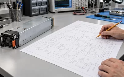
The G1505-3200WNA is a 3200 W, 12 V hot-pluggable CRPS module in a 185 × 73.5 × 40 mm enclosure. Powernexu lists a maximum output current of 266 A and an AC input range of 90–264 V. The practical question for a server builder is how to move that much current from the module through its mating board to several loads without excessive voltage drop, contact heating, or a single overloaded branch. The published dimensions and rating are useful screening data, but they do not establish a compatible connector, a full-power input condition, or a complete distribution design. This article focuses on the 12 V power path that makes a high-current CRPS installation work.
What 266 A means at the edge connector
At nominal 12 V, 266 A represents about 3.19 kW. That arithmetic is consistent with the listed 3200 W class, allowing for rounding; it does not describe a measured operating point. The current passes through the module-to-backplane interface before it divides among the server’s branches. Consequently, the first centimeters of the path deserve particular attention. A narrow copper neck, insufficient parallel contacts, or an uneven mating surface can create a hot spot even if each downstream cable appears comfortably sized.
Consider a hypothetical total path resistance of 0.5 milliohm between the PSU output and the first distribution node. At 266 A, the resistive loss is I²R, or roughly 35 W, and the voltage drop is about 0.133 V. These are illustrative calculations, not measurements or specified limits for the G1505-3200WNA. A few milliohms that might seem negligible on a low-current board become consequential here. The designer therefore needs actual contact, copper, and interconnect resistance estimates at operating temperature. The allowable drop follows from the input tolerances of the downstream regulators, not from an arbitrary percentage selected for the article.
The G1505-3200WNA product listing gives the headline electrical and mechanical values. Its manufacturer, Gospower, places the related G1505-3200W in its T185 Titanium CRPS series. The family description mentions a 12.2 V output and built-in ORing, but those family statements should be confirmed against the exact purchased suffix and revision before being treated as a model-specific guarantee. Powernexu’s own G1505-3200WNA product page is the appropriate starting point for its listed 12 V, 266 A and size data.
Build the 12 V distribution tree from the loads backward
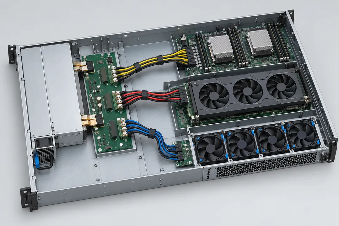
Server boards rarely present one uniform 266 A load. CPU voltage regulators, accelerator carriers, memory power stages, drives, fans, and management circuitry draw from different branches and change load at different rates. A useful distribution drawing begins with each branch’s continuous current, peak current, connector, protection element, and physical route. It then identifies where currents combine. A trace or busbar near the PSU may carry the sum of several branches; a harness to one accelerator tray carries only that tray’s demand. Treating every segment as if it carried the nameplate current can waste space, while sizing a shared segment for one branch can create an avoidable bottleneck.
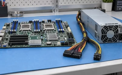
The first design decision is whether the host uses a rigid PDB, a busbar, a cable assembly, or a combination. A rigid board can shorten the high-current path and provide repeatable connector alignment. A busbar may be attractive where large current travels across a chassis. Cables can route around obstacles but introduce crimp, terminal, bending-radius, and service-clearance questions. None of these forms is intrinsically superior. The appropriate arrangement depends on the chassis layout, the number of load zones, the allowable drop, the fault-protection scheme, and the cooling path around the conductors.
In a GPU server, the branch to an accelerator carrier deserves its own analysis. The carrier’s regulator input may respond to rapid workload changes; the bus capacitance, PDB impedance, and protection element affect the voltage seen at that input. A module’s 3200 W continuous rating does not specify the permissible GPU power excursion or the voltage waveform at the card. If a branch trips while the whole PSU remains within its nominal rating, the problem may be local to the branch protection or distribution impedance rather than the source’s total capacity. That distinction directs troubleshooting toward the right measurement points.
Low-line input is a separate capacity question
The 90–264 V AC input range identifies where the listed product may accept AC power. It does not establish that 3200 W output is permitted at every voltage within that range. High-output CRPS units frequently have input-dependent ratings, and this model’s public Powernexu summary does not provide a detailed power-versus-input table. The engineering requirement is to obtain the revision-controlled datasheet for the exact G1505-3200WNA and identify the continuous output available at each intended supply condition.
This matters when one server design is deployed in sites with different rack feeds. A chassis that works on a high-line data-center circuit could exceed its allowable PSU output at low line even though the module accepts the voltage. Branch-circuit protection, PDU outlet rating, connector rating, and rack capacity also need to accommodate the AC input current under the approved operating point. Dividing 3200 W by a nominal wall voltage would understate input current because the converter has losses and its power factor and operating conditions matter. Use manufacturer input-current data for wiring and protection decisions.
For procurement, ask the supplier to specify the exact input condition associated with the 3200 W nameplate, any derating with temperature or altitude, and the permitted standby-plus-main output combination. Record the expected site voltage and tolerance in the equipment bill of materials. If the system may fall back to a lower-voltage source during a power event, evaluate the fallback condition as an operating mode rather than a rare exception that can be ignored. The design may need a lower software power cap or a different module count in that mode.
Two modules create a different 12 V network
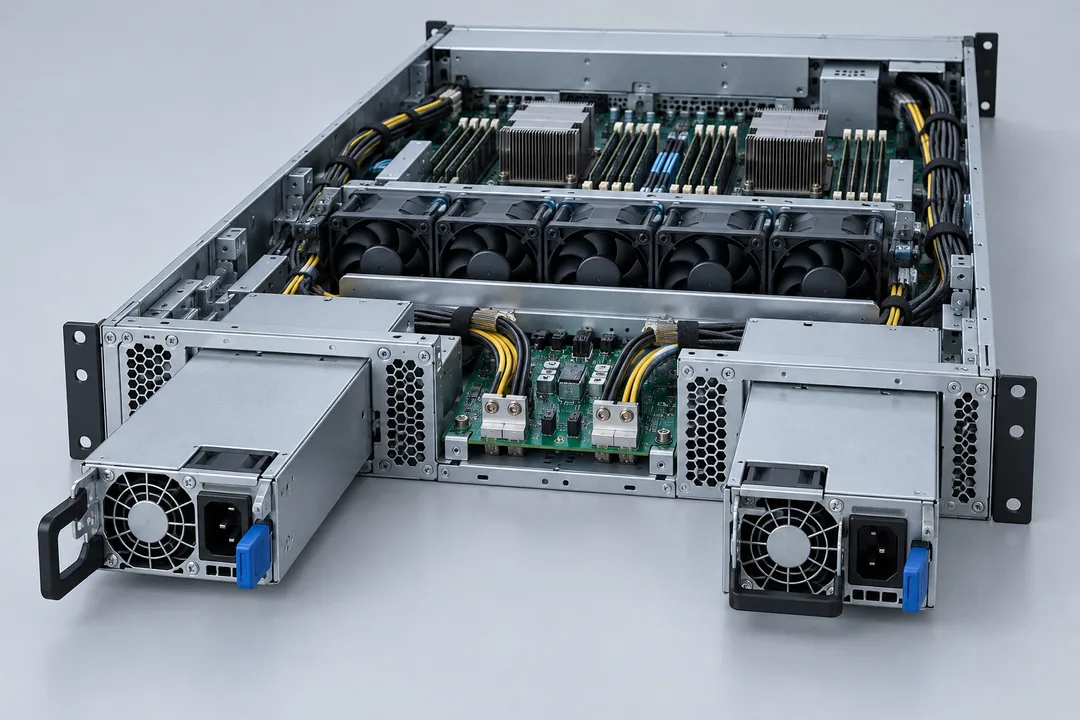
Installing a second CRPS module can provide continuity after a module is removed or fails, provided the chassis, PDB, and control implementation are designed for that behavior. A nominal pair of 3200 W modules should not be interpreted as 6400 W of 1+1 redundant capacity. To survive the loss of either module without shedding load, one remaining unit must support the total server demand under the relevant input and thermal condition. This requirement is especially significant when a rack feed changes from high line to low line.
The shared 12 V node also needs controlled fault isolation and current sharing. Gospower describes built-in ORing for its T185 family, but the module’s actual implementation, interaction with the host PDB, and permissible transient during a module fault belong in the exact technical documents. ORing prevents one faulty source from pulling down a healthy source only when the protection and distribution architecture behave as intended. It does not protect against every common-mode event, such as a short on the shared bus or loss of the sole upstream PDU.
Hot-plug capability means a suitable system can support insertion and removal under its specified conditions; it is not permission to pull a unit while the surviving path lacks capacity. Before defining a service procedure, establish the pre-removal load, the surviving-module rating, the AC feeds serving each bay, and the status indicators that confirm healthy operation. During insertion, contact sequencing and inrush control should prevent an unacceptable disturbance on the active 12 V bus. Those details are determined by the qualified module and chassis combination, not by a generic CRPS silhouette.
The same outer dimensions do not prove interchangeability
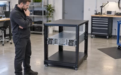
The listed 185 × 73.5 × 40 mm outline is an initial mechanical filter. It does not show the location and geometry of every guide rail, latch, handle, connector, and clearance feature. A 12 V CRPS from another family may slide toward the same bay yet differ at its final mating interface. Check the module and host drawings together, including insertion travel, retention, extraction access, and the rear-panel space needed for a technician’s hand. Alignment errors at a high-current connector can increase resistance and heating before a visible fault appears.
Electrical interchangeability is stricter than physical fit. Confirm the power-contact assignment, number and rating of contact positions, standby rail, enable and power-good signals, sense wiring, management interface, and any vendor-specific identification behavior. The public listing does not expose the G1505-3200WNA pinout, so a pin map copied from another CRPS model would be an unsafe substitute. A distributor lists the model with a gold-finger cable type and PMBus support, but the exact connector and register behavior still need the approved specification for the intended revision.
A 54 V CRPS of similar size is an especially clear counterexample. Its 54 V main rail is architecturally different from this model’s 12 V output. The nearby CRPS3200TS5 article addresses the 54 V distribution path; swapping the two by wattage or envelope would put the host’s electronics on the wrong bus. For the G1505-3200WNA, focus instead on whether the existing 12 V PDB can carry the required current and whether its control and mechanical details match.
Heat follows both the converter and its contacts
Gospower describes the T185 family as Titanium CRPS. An efficiency class is useful for comparing qualified operating points, but it does not provide one universal loss figure for every input, load, and environment. The exact efficiency curve matters if rack energy or cooling is being estimated. Converter loss is only part of the heat near the module: edge contacts, PDB copper, busbars, protection devices, and branch connectors add their own I²R losses. A cool PSU exhaust does not prove that the high-current contact zone is cool.
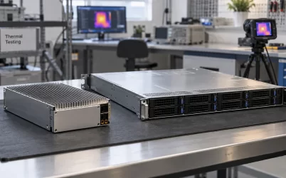
The module’s compact 40 mm height also makes airflow direction and obstruction practical concerns. A server intake, neighboring module, cable bundle, or dust filter can change the air that reaches the PSU. Obtain the approved airflow direction and intake-temperature limits for the exact unit; do not infer them from a product photograph or a different T185 suffix. A chassis may keep the converter within its thermal limits while a densely packed PDB contact operates too hot, so both areas need attention.
Temperature changes conductor resistance and can expose weaknesses in a connection that appears adequate during a short bench run. If the server is being qualified, measure voltage drop and temperature along the loaded distribution path after thermal stabilization. Focus on connector transitions, branch takeoffs, and the return path. These observations reveal whether heat is concentrated in a particular interface rather than uniformly distributed. The test conditions should match the intended input voltage, server workload, airflow state, and redundancy mode.
What a meaningful integration package contains
Before committing the G1505-3200WNA to a server platform, obtain the model- and revision-specific datasheet, mating connector drawing, output derating data, control-signal definition, and approved environmental limits. Map those documents to the actual host board revision. For a purchased spare, record the exact suffix and revision because changes to connector details or firmware behavior may matter even when the product name is familiar.
The next deliverable is a measured 12 V path, from the module output to the farthest or most demanding regulator input. Define where voltage is measured, which branches are active, and whether the system is in normal or one-module operation. A voltage reading at the PSU alone can miss a drop on the PDB. A current reading for the total server can miss an overloaded local branch. Paired measurements at both ends of each critical segment make the causes of a failed load transition easier to isolate.
Finally, document the operating conditions under which the server’s advertised capacity is valid. A high-line feed, a stated intake-temperature range, a specific number of installed modules, and a defined redundancy objective may all be part of that statement. This turns a 3200 W part number into a usable system specification. The G1505-3200WNA is a strong candidate for a compact, high-current 12 V server bay when its verified input envelope and connector match the host; its usefulness is realized through the design of the complete 12 V path.