A server power supply schematic is not just a picture of an AC input feeding a 12 V output. It is a map of energy conversion, isolation, control, standby power and fault behavior. A search for one often begins with a practical question: where does power go after the inlet, which circuits stay alive when the server is off, and why does a fault in one stage remove an otherwise healthy output? A useful reading method follows those paths without pretending that every server PSU uses the same topology.
There is an important distinction between a functional block diagram and the electrical schematic of a particular model. A block diagram explains functions and interfaces; a model schematic specifies components, nodes and connections. The latter may be proprietary, and a drawing from one reference design is not the wiring plan for another supply. This article uses published reference-design material to explain how to interpret common blocks, not to offer a repair procedure for energized equipment.
Start at the boundaries, not at the smallest component
Before following a switching transistor or control IC, locate the input connector, protective earth, primary-to-secondary isolation boundary and output connector. Then identify the rated input type and output rails. This prevents a basic reading error: treating every node marked “ground” as the same electrical conductor. Primary-side return, secondary output return, chassis and protective earth can have different roles. Symbols may be connected by controlled components or safety-rated capacitors without being a direct power connection.
The input may be AC mains, high-voltage DC or a lower-voltage DC distribution feed. These are different architectures, not interchangeable names for the same inlet. An AC front end commonly includes input protection, filtering, rectification and a power-factor-correction stage before an isolated converter. A DC-input design may omit some of those functions or use a different front end. A schematic must be read against its named input range and reference platform before any block is generalized.
Also inspect the drawing legend and sheet boundaries. Large power systems often split the schematic into a main converter sheet, an auxiliary-supply sheet, a control board, a connector page and a distribution-board page. A missing load connection may be on another sheet rather than absent from the system. A bus connector symbol is a boundary: the motherboard and power distribution board can determine how the PSU output is switched, shared and monitored after it leaves the module.
The AC front end has three distinct jobs
On an AC-input reference schematic, an input filter limits conducted noise in both directions. It may include differential and common-mode filtering elements, along with protective and safety components selected for the target equipment. Filtering does not by itself regulate the output. A bridge or equivalent rectification circuit then produces a unidirectional high-voltage bus. The active power-factor-correction stage shapes input current and controls its own intermediate bus. Those three jobs can be drawn close together, but they answer different questions.
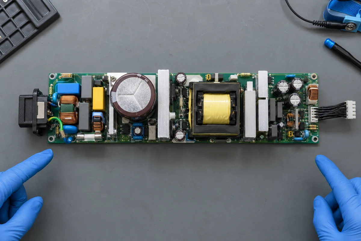
Look for the large bulk capacitor after rectification or PFC. It marks an energy-storage node, not a harmless “off” point. The voltage on that node may remain hazardous after input removal; its discharge behavior is a safety matter governed by the actual design. A schematic that shows a bleed path is not permission to touch a supply. Do not infer a safe waiting interval from a generic drawing. Server PSU work at this level belongs to qualified personnel following the exact manufacturer’s service instructions and applicable safety procedures.
The front-end control loop senses relevant voltage and current quantities and drives switching devices to manage the intermediate bus. It may also enforce input brownout or overvoltage behavior. A fault indication near this stage therefore does not prove that the downstream isolated converter is defective. The operating sequence matters: if the intermediate bus never rises correctly, the second converter may never receive permission or sufficient energy to start.
Trace the isolation barrier and the regulated output
The main isolated stage transfers energy through a transformer or another appropriate isolation structure while regulating the output. Its exact power topology varies with the design. A schematic might use an LLC resonant converter, a phase-shifted full bridge or another arrangement. Rather than label any transformer-connected switch network “LLC” on sight, identify the switching nodes, resonant or energy-storage elements, transformer connections, rectification and controller feedback described in the original design documentation.
On the secondary side, rectification converts transformer output into DC; synchronous devices are common in high-current designs because conduction loss matters. Output filtering then reduces ripple and supports transient behavior. The output voltage is regulated by feedback crossing the isolation boundary through an appropriate method. The sensing point matters: regulation at the module connector is not the same as regulating directly at a distant load after a PDB, busbar and cable drops. Some platforms provide remote-sense lines, but their existence and permitted connection must come from the actual interface specification.
A published 220 W server-supply reference design from Monolithic Power Systems includes a full electrical drawing. It illustrates the value of reading across blocks: controller components, power magnetics, isolation, feedback and output circuitry appear as a connected system rather than as a single “PSU” rectangle. Its values and topology describe that reference design. They should not be lifted into a higher-power server module or assumed to match an unrelated commercial product.
Consider a simplified example. Suppose the output rail falls only when a GPU load changes sharply. The drawing suggests several plausible paths: the load step may exceed the converter’s transient response, output distribution may introduce enough voltage drop to disturb the load, a current limit may intervene, or a control signal may be changing the module state. The schematic helps locate measurement and interface boundaries; it does not identify the cause without synchronized system measurements. A single low reading at the motherboard is not proof of a failed output stage.
The standby supply explains why “off” does not mean unpowered
Many server supplies include an auxiliary or standby converter that operates whenever valid input is present, even when the main output is not enabled. It can power module control, communication or a standby rail used by the host. In a schematic, it may branch from the input or high-voltage bus and appear on a different sheet from the main power train. Its smaller apparent power does not make it optional: without it, the controller or host may be unable to request the main output.
Follow the enable sequence as a separate path. Input-valid detection allows the auxiliary supply to establish bias. A host signal or internal condition then permits the main converter to start. Output-good and fault signals report states back to the system. Timing, polarity and connector assignments are model-specific. A block labeled “PSON” or “PS_ON” in one source must not be assumed to have identical semantics in another. Nor should an engineer bypass an enable line merely because a generic diagram appears to show a simple switch.
Standby behavior changes troubleshooting logic. If the server’s management controller remains alive but the main 12 V bus is absent, the input path and auxiliary supply may be operating while the main stage is disabled or faulted. If no management response exists, the problem could be upstream of standby power or in the host’s distribution path. These are hypotheses, not diagnoses. The actual connector specification, telemetry and safe service method determine the next observation.
Control lines are part of the power system
A removable server PSU can expose far more than positive and negative output terminals. Presence, power-good, enable, current-share, remote sense and management-bus signals may all cross the module connector. Their exact collection depends on the platform. Read each signal’s direction and reference carefully. A controller output from the PSU is not interchangeable with a host command input, and a low-voltage signal return should not casually be tied to chassis or the primary circuit.
Digital management adds another layer. PMBus or an implementation based on it can expose operating data and faults, but a protocol label does not make two modules interchangeable. Addressing, command support, scaling, firmware identification and host interpretation all matter. A schematic can reveal that a communication path exists, yet it cannot alone establish that a specific BMC will accept a particular replacement module. That requires the controlled interface information for the host and module.
In redundant systems, a current-share connection helps modules divide normal load. Isolation or ORing elements protect the common bus against some faults. These functions may reside in the PSU, PDB or both, depending on architecture. The schematic boundary is therefore important: if only the PSU sheet is available, the reader cannot conclude how the complete 1+1 system handles a shorted module, an empty bay or loss of one input feed. The PDB and host control drawings complete that picture.
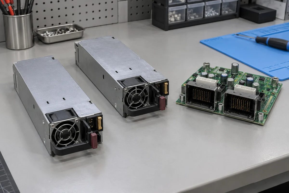
A diagram with two identical PSU rectangles joined at a bus should not be read as “twice the protected power.” In a 1+1 system, each surviving path must carry the required load after the other is lost, subject to its actual input and thermal conditions. The drawing can show a parallel connection but cannot substitute for the module’s output rating table, derating curves and host-supported redundancy mode.
Protection circuits reveal where the supply stops trying
Input protection, overcurrent sensing, output overvoltage protection, thermal shutdown and fan monitoring can appear in different sheets. Each senses a different quantity and may respond by limiting, latching off, retrying or reporting a warning. Do not infer behavior solely from the presence of a comparator or sensor symbol. Read the associated controller description and firmware behavior where available. A thermistor shown near a heatsink is evidence of one sensing location, not a complete map of temperatures inside an installed chassis.
Protection and redundancy interact. A PSU that enters current limit during a transient may make the other module carry more load; a host may throttle, alarm or shut down depending on its policy. The same symptom can arise from a shared output-path issue, an input sag, a fan fault or a management-state change. A schematic helps divide these into observable stages: input bus, intermediate bus, isolated output, distribution bus and host load. It does not guarantee that every stage has an accessible test point in the assembled server.
What a schematic can and cannot establish
A specific electrical drawing can establish circuit connectivity and help explain intended control behavior. It can identify where isolation occurs, what senses a voltage, how an auxiliary rail starts, and which connector pins communicate with the host. It does not by itself prove efficiency, acoustic performance, electromagnetic compatibility, safety approval, replacement compatibility or thermal performance in a particular rack. Those claims need their own measurements, certifications or platform documents.
Keep three levels separate when comparing sources. At the component level, a controller application note illustrates one implementation. At the module level, a manufacturer specification states input, output and protection behavior for a named PSU. At the system level, the server’s technical specification describes the connector, PDB, firmware, airflow and redundant modes. A claim from one level cannot automatically be promoted to another. The 220 W reference drawing above is useful for learning feedback and power-stage relationships; it is not a compatibility record for a commercial server.
The safest way to use a server power supply schematic is therefore to ask a precise question of it. Where does the intermediate bus originate? Which supply feeds the control circuit before the main rail starts? Where is feedback sensed? Which protection signal can disable the converter? What leaves the module and enters the PDB? If the available drawing cannot answer the question at the correct system level, look for the missing manufacturer or host document rather than inventing the connection. A schematic is most powerful as an exact map of one design, and most misleading when treated as a universal server-PSU wiring plan.