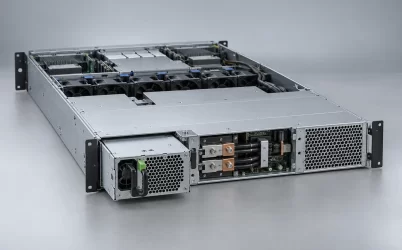
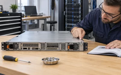
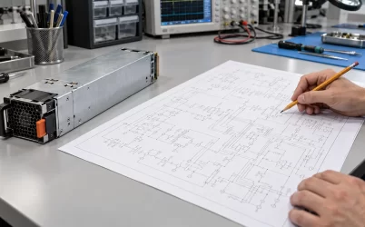
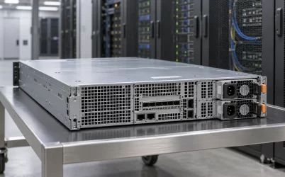
Server PSU cooling depends on the air that actually passes through the power module, not simply on how many fans a chassis contains. The module converts electrical power and releases the conversion loss as heat. Its fan, the server fan wall, bay geometry, air baffles, and rack inlet conditions determine whether that heat leaves the enclosure. A supply can be electrically adequate yet run hot if the host sends air the wrong way, an empty bay opens a bypass, or a warm rear recirculation path reaches its intake. Cooling therefore belongs to the supported server configuration, not to a wattage label alone.
Track the air through the PSU, not just across the server
Imagine following one parcel of inlet air. It enters the server at an opening chosen by the chassis designer, passes through a channel shaped by drives, boards, and baffles, reaches the PSU intake, crosses the converter’s internal resistance, and exits into an exhaust region. A fan can move large total volume while too little of that flow enters one narrow branch. The useful question is not “Is there airflow?” but “What air, at what temperature and pressure, reaches this PSU under the installed configuration?”
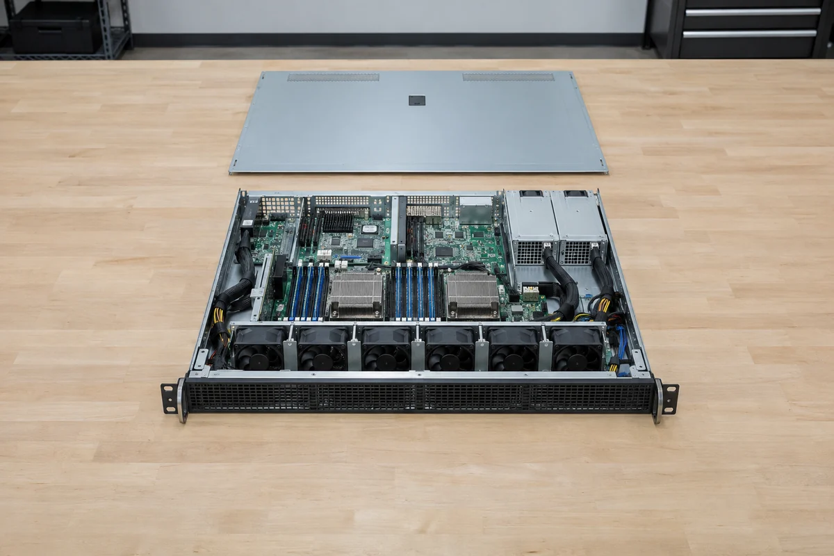
Different servers answer differently. A removable PSU may have its own fan drawing air through the module. A chassis fan wall may supply most of the pressure while the PSU fan helps at particular operating points. Some platforms combine both. Fans in series and parallel do not respond identically to grille resistance, a dirty filter, or a blocked outlet. That is why the host’s supported thermal design, including the specific module and its airflow direction, matters more than a generic fan diameter or advertised free-air flow rate.
The power distribution board can share the same air path. An Intel chassis technical specification illustrates this dependence by describing a PDB whose converters receive air from the PSU modules and sit in the same series path. That is one platform example, not a universal layout. It shows why moving a module, changing a cage, or installing a fan with the opposite direction may raise temperatures outside the PSU itself. The thermal system includes nearby electronics and conductors, not just the converter’s hottest semiconductor.
At a rack level, cold-aisle temperature is only an upstream boundary. The module inlet can be warmer if other equipment preheats the air, if an open gap lets exhaust return, or if cables obstruct the intended channel. A server inlet probe elsewhere in the chassis may not see the same condition as the PSU inlet. Position-specific measurements are therefore useful when investigating a thermal alarm or qualifying an unusual enclosure; they answer a more specific question than the room thermostat.
The fan curve meets the chassis resistance
Airflow is produced where the fan’s pressure capability intersects the resistance of the actual path. A tight grille, dense heatsink, narrow PSU cage, dust mat, or sharp turn increases that resistance. A fan’s free-air specification describes a different condition and cannot be treated as the installed flow through a server module. This relationship explains a common surprise: replacing a fan with another unit of similar nominal airflow may not maintain the same cooling if its pressure curve or control behavior differs.
Small power modules place components close together, so uneven flow matters. A local region behind a transformer, inductor, heatsink, or connector can remain hot even when the exhaust stream appears moderate. The module’s own sensors may command more fan speed based on one internal temperature; the server controller may respond to a different sensor. Fan control coordinated by the host must be considered alongside the PSU’s internal behavior. Otherwise, one controller may assume the other is supplying an airflow level that never arrives.
The design should also account for the direction of airflow. A rear-to-front PSU installed in a front-to-rear server can oppose the intended channel or introduce local recirculation. Two modules may be the same mechanical shape and output rating but have different fan direction. A management interface can report that both modules are present and healthy while the airflow arrangement remains wrong. The service spare list should therefore identify the correct airflow variant rather than relying on appearance alone.
Rack furniture adds another pressure and recirculation layer. Doors, blanking panels, cable management arms, and rear clearances influence where exhaust goes. A dense bundle immediately behind a PSU grille can increase backpressure and warm the cable area. Removing rack doors or moving cables might change symptoms, but those changes are diagnostic clues, not automatically approved permanent fixes. The finished installation must meet the host’s documented cooling and service conditions.
Conversion loss sets the heat load but not the temperature
The power dissipated inside a PSU is approximately the difference between its input and useful DC output. If a module delivers 1,000 W at a measured 95% efficiency, its input is about 1,053 W and its conversion loss is about 53 W. This calculation describes heat generation in the converter at that operating point. It does not tell us the temperature of a component or predict the needed fan speed. Those require the airflow path, ambient conditions, internal thermal resistance, and control strategy.
A redundant pair changes where the heat appears. If two modules share a load evenly, each processes only part of the total output and each sits at its own point on an efficiency curve. After one module fails or is removed, the surviving supply processes more load and can dissipate more heat in one compact bay. The removed module’s fan may also stop contributing to chassis airflow. Electrical redundancy can preserve operation while the thermal state becomes more demanding. The one-module condition should be understood as a different airflow and loss arrangement, not merely a doubled number on a power spreadsheet.
In a hypothetical comparison, two modules each dissipating 30 W create 60 W total, while one surviving module might dissipate a different amount at the full load. One cannot assume it is exactly 60 W or twice 30 W: conversion efficiency changes with load, and fan power may change too. The point of the example is that total heat and the location of that heat both matter. A rack may remove 60 W in normal operation yet struggle with a similarly sized heat source concentrated behind one blocked grille.
Input voltage can affect the thermal story as well. Some exact PSU models change available output or internal losses across their supported AC range. At a lower source voltage, the input current needed for a given power can be higher, changing losses in the inlet and power path. This should not be generalized into a universal derating figure. Use the module’s documented input and thermal curves, and distinguish a safe operating rating from a best-efficiency operating point.
Empty bays and missing baffles can defeat a healthy fan
Air prefers lower-resistance routes. If an unused PSU bay is left open where the chassis expects a blank, some fan flow can bypass the intended components. The open slot may also let rear exhaust recirculate toward an inlet. The effects depend on the chassis layout and pressure field, but the failure mechanism is simple: a missing physical boundary changes the path. A server can report normal fan speed while less cool air reaches the installed PSU or adjacent PDB.
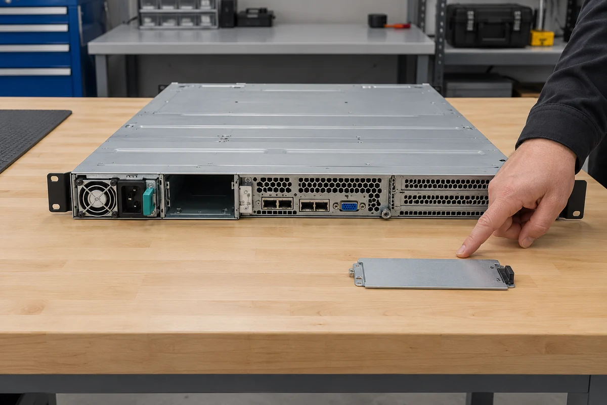
The same mechanism applies to missing drive blanks, misplaced air ducts, and poorly seated covers. A spare part that seems unrelated to power can redirect flow through the power cage. For this reason, platform population rules are thermal instructions as well as mechanical housekeeping. An otherwise compatible PSU tested in an open bench fixture is not necessarily qualified for a fully populated 1U server, and the opposite can also be true if the bench exposes the module to more cool air than the closed chassis provides.
Hot swapping introduces a temporary open state. A supported service procedure may tolerate that state for a defined period or under defined loads, but neither duration nor safe power can be invented for a generic server. If maintenance leaves a bay empty for longer than intended, the airflow change can become a sustained condition. The correct replacement assembly may include a bay blank or airflow barrier; its function should not be dismissed as cosmetic.
Dust is another path modifier, not merely dirt on a visible fan. A deposit on a grille raises resistance; a layer on internal surfaces can impede heat transfer. Replacing a noisy fan without finding a clogged intake may temporarily change the symptom while leaving the root cause. Cleaning procedures should follow the equipment maker’s instructions, particularly around removable modules and energized enclosures. A server PSU is not a device to open casually for a fan or dust repair.
Read thermal symptoms in the order they occur
A PSU thermal problem can present as higher fan speed, acoustic change, an overtemperature warning, power derating, a protective shutdown, or apparently unrelated server throttling. The order of events matters. A fan speeding up after rack inlet temperature rises suggests one chain; a sudden PSU warning after a module exchange suggests airflow variant, seating, or control compatibility. A warning only when a second module is withdrawn points toward the surviving-state load and flow arrangement. None of these patterns proves the cause by itself, but each narrows the physical investigation.
Start with read-only evidence where possible: rack inlet environment, BMC and PSU telemetry, fan-status history, module identities, current load, and any recent hardware change. Compare what the host reports with what is physically installed. A missing sensor reading is not the same as a normal temperature, and a reported fan RPM is not a direct airflow measurement. A tachometer can confirm that a rotor spins while a blocked path still starves the converter.
Location matters when measuring. A probe at the server front, one at the PSU intake, and one near the rear exhaust answer different questions. High exhaust temperature with a cool intake can indicate substantial local loss or restricted flow; a warm intake can indicate upstream preheating or recirculation. Neither observation alone yields an internal component temperature or proves the PSU defective. Use the maker’s sensor definitions and safe measurement points before drawing a conclusion.
A replacement test should avoid changing several variables at once. Swapping both PSU module type and fan direction while moving cables and removing a rack door makes it hard to identify the actual cause. It is better to preserve the approved configuration and isolate the recent change, with qualified personnel following the platform service procedure. Where the exact module is no longer available, a proposed substitute needs a thermal as well as electrical compatibility case.
Cooling capacity must survive the server’s service states
The meaningful cooling envelope includes the server at normal load with all modules installed, the highest supported sustained workload, a single-surviving-PSU state where redundancy is promised, and the supported maintenance arrangement. Each state changes the heat distribution or the available airflow. A server that passes at room temperature with two clean fans may not behave the same in a warm rack, with a blocked rear grille, or with one PSU bay open. That does not mean every scenario demands a new generic checklist; it means the platform’s own thermal limits must cover the state being claimed.
Good server PSU cooling ultimately has a spatial answer. Cool air must reach the module inlet, cross the converter and nearby PDB as intended, and leave without returning to the intake. The installed fan and host control must provide enough pressure along that path under the supported load and ambient conditions. Once those physical relationships are clear, a wattage rating, efficiency curve, or fan-speed reading can be interpreted correctly. Without the path, each number is only a partial description of a thermal system.