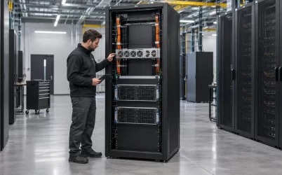
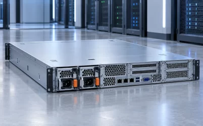
Server PSU grounding and bonding are related but different parts of electrical safety. Protective earthing connects an equipment enclosure to the installation’s protective system so a fault does not leave accessible metal at a dangerous potential. Bonding joins conductive parts that need an effective common protective path. Neither is the same as the PSU’s DC output return, a management-bus reference, or a convenient screw on a rack rail. The correct path depends on the exact AC- or DC-input server, its approved installation instructions, and the building supply. Do not add or remove a bonding conductor based only on a generic PSU diagram.
Follow the protective path from source to accessible metal
In an AC-powered rack server, the source normally arrives through a grounded cord and an approved inlet. The protective conductor is intended to connect to the equipment’s protective structure; the live and neutral conductors serve a different function. The PSU case, cage, server enclosure, and rack may have designated bonding relationships, but the actual fault path is defined by the product and installation design. Metal touching metal is not proof of a dependable protective connection. Coatings, moving rails, removable parts, loose hardware, and corrosion can change contact quality.
A DC-powered version may have a different entry arrangement. Some product documentation explicitly calls for a chassis earthing or bonding connection before its DC source is attached. Others integrate protective connections into a defined input assembly. These arrangements cannot be inferred from the fact that the server has a DC-input PSU. The manufacturer must identify the terminals, conductors, order of connection, and conditions of use for that platform. An installer must then apply the relevant local electrical requirements and approved procedure.
The safety objective is not to create a cosmetically tidy cable route. It is to maintain an effective safeguard if insulation or another barrier fails. IEC 62368-1 describes safety for information and communication technology equipment through energy-source classification and safeguards; its official publication record makes clear that it is an equipment-safety standard, not a performance specification. Compliance of one PSU component does not automatically establish that a server assembled with a new cage, cord, or DC feed has the intended protective path. The completed equipment and its installation instructions still matter.
A simple way to reason about the architecture is to name every boundary: building protective system, rack distribution, supply cord or DC feed, PSU enclosure, host chassis, and any separate rack bond. The drawing should show which connections are explicitly protective and which merely carry operating current. If the proposed path relies on drawer slides, a random mounting bolt, or a signal cable shield, that is a warning to consult the approved design rather than treating incidental contact as a qualified bond.
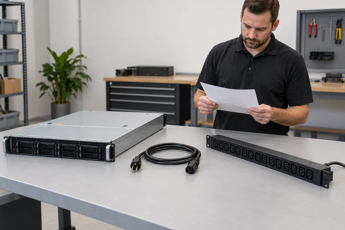
Do not confuse protective earth with the DC output return
The DC output return is part of the functional power circuit. It carries load current back from server electronics to the converter. Protective earth is part of a safety system for accessible conductive parts. Depending on PSU topology and equipment design, the two may be isolated, connected at a controlled point, or related through components that manage noise. There is no universal rule that a server’s 12 V return should be hard-bonded to its rack at an arbitrary location.
A forced return-to-chassis connection can create unintended circulating current, bypass a designed sensing path, or defeat an isolation assumption. Leaving a required protective connection open creates a different problem: a fault may not have the intended low-impedance route. Those are not opposite answers to the same question. They concern different conductors with different purposes. The only defensible connection plan starts with the PSU and host electrical documentation, including whether the output is isolated and where any reference or bond is intentionally made.
The same distinction applies to management signals. PMBus or other telemetry may use a signal ground or reference shared with an electronics domain. That reference is not an equipment protective conductor. A signal connector can show continuity to chassis through filtering or protective components without being suitable for fault current. A service technician should not infer a safe protective path from a continuity reading taken across an unspecified signal pin, nor infer that two domains should be tied together because a meter reports some connection.
For redundant supplies, two modules may feed a common PDB and share the output return while receiving AC from separate rack PDUs. The intended protective connections for both input feeds must remain intact even if one module is removed. Load sharing and output combining do not substitute for grounding. Likewise, separating the two AC feeds for availability does not mean creating two isolated, casually improvised equipment grounds. The facility and equipment designs specify how exposed metal remains protected throughout each operating and service state.
Removable PSUs create a moving protective interface
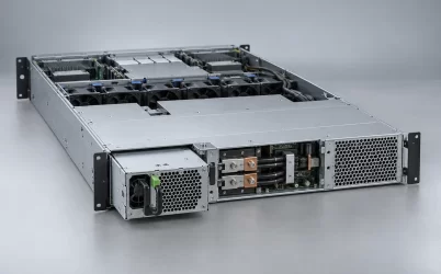
A hot-swap module can be extracted while the host continues operating from another supported module. That service feature makes the mechanical-to-electrical sequence important. The design must account for how the module enclosure, mating connector, and host cage maintain their intended protective relationships as contacts engage and disengage. A narrow power blade or latch may be visible, but its appearance does not reveal which contact provides an intended protective connection or when it mates. Connector sequencing belongs to the exact platform specification.
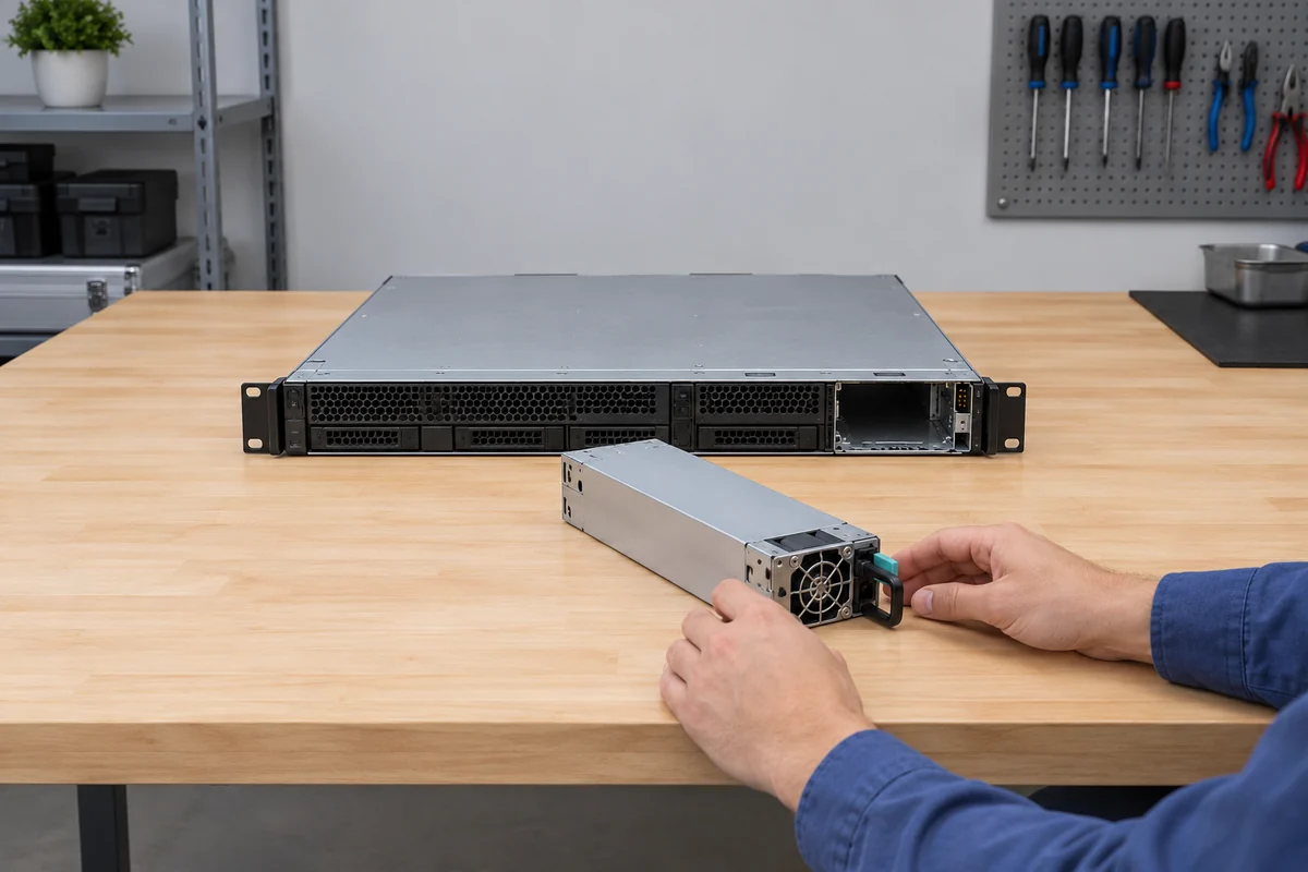
Consider a fault inside one module. The operator may need to remove that module while the other continues carrying the server. The intact module, chassis, and rack must retain their documented protective paths. A loose cage bond, damaged inlet, or incompatible replacement could change the fault behavior even if the server still boots. Functional operation is therefore weak evidence of protective integrity. A server can appear healthy while an enclosure connection is compromised.
Mechanical details that look minor can be consequential: paint beneath a designated lug, missing star washers where specified, damaged contact fingers, an incorrectly seated module, or a replacement cage with a different bond feature. The point is not to recommend a universal hardware fix. These examples explain why an approved replacement part and assembly procedure matter. Some equipment uses a dedicated bonding strap; other equipment achieves the path through listed enclosure and connector assemblies. Copying a strap from another server family may be just as wrong as omitting one.
Chassis service can also disturb connections outside the PSU. Sliding a server out on rails, replacing a PDB, or changing a rack PDU may alter paths that were present before work began. A protective conductor must not depend on a signal harness simply because that harness happens to stay attached during maintenance. Good service documentation identifies which connection is safety-critical, which may be disconnected under power, and what conditions are required before return to operation.
The rack bond and the server bond are not interchangeable
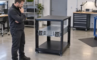
A metal rack has its own conductive structure and may have a designated bond to the installation grounding system. Servers and power distribution equipment mount within it. That does not turn every rail contact into an approved protective conductor for every server. Conversely, a grounded AC cord on one server does not automatically prove that the complete rack, its doors, side panels, cable trays, and DC equipment have the intended bonding arrangement. Each item has its own design and installation requirements.
The practical question is where a fault current would return and what protective device or safeguard would respond. A rack bond can help keep accessible metal at a controlled potential, but it should not be treated as a replacement for a missing supply protective conductor unless the equipment’s approved instructions explicitly define that arrangement. Multiple racks, A/B feeds, UPS outputs, and DC plants make assumptions about common reference especially risky. Those interfaces are part of facility electrical design and should be reviewed by qualified personnel.
Some server products support different bonding-network arrangements for specialized installations. The existence of such options is not permission to switch between them informally. The approved configuration, source topology, and local code determine how the server is connected. For example, a rack assembled for a conventional three-wire AC feed may require different equipment and procedures when converted to a DC-input platform. The PSU’s rated output wattage does not answer any of those questions.
It is useful to distinguish three visual checks, without mistaking them for a complete safety test. First, identify the designated protective terminal or integrated path in the equipment documentation. Second, verify that the installed cord, feed, chassis, and rack components match that documented configuration. Third, make sure the service state has not removed a required connection. Electrical continuity, conductor sizing, fault-loop performance, and acceptance criteria are application-specific and should be tested under the governing procedure, not improvised from a blog checklist.
Electrical noise is a separate reason to care about layout
Grounding and bonding also influence electromagnetic behavior, but safety and noise control must not be collapsed into a single slogan. A converter has fast switching currents. Cable shields, enclosure seams, filters, and controlled return paths can affect conducted and radiated emissions. A poor chassis connection can worsen noise performance even when the DC output appears stable. Yet a connection made solely to quiet a measurement must not compromise the protective design or produce an unintended load-current return.
In a rack with multiple servers, storage systems, and network devices, differences in reference potential can affect sensitive interfaces. The solution is not automatically “more ground wires.” Extra bonds placed without a defined scheme can create loops or bypass intended isolation; too few or damaged bonds can leave gaps. The installation drawing should separate protective conductors, functional signal references, shield terminations, and DC returns. That clarity allows a noise problem to be diagnosed without moving a safety conductor as an experiment.
After a PSU change, a new noise symptom may arise from a different filter topology, cable position, connector condition, or chassis contact. That symptom does not prove that the new PSU is unsafe, nor does its absence prove that the bonding is correct. EMC behavior and protective integrity require different evidence. When troubleshooting, preserve the approved protective connections while tracing functional noise paths through the actual equipment design.
What to establish before changing a server power configuration
The grounding question becomes concrete when a PSU, cage, host platform, input feed, or rack distribution part is replaced. Identify the exact assembly and its approved AC or DC input configuration. Determine the documented protective connection from source to enclosure and rack; separately identify the DC output return and management reference. A replacement module must match not just power and pinout but also the host’s mechanical and safety interface. If those facts are unavailable, an apparently fitting module is not evidence that the revised system is safe to energize.
For an AC server with approved modules, the intact grounded cord, inlet, enclosure, and rack installation may already provide the prescribed arrangement. For a DC server, a dedicated bonding or earthing step may be required before the source is connected, as platform-specific manuals illustrate. The right answer is in the applicable equipment instructions and local electrical design, not in a universal rule that all racks need an extra wire or that every PSU grounds itself.
Grounding and bonding should therefore be described as a continuous protective design across the source, PSU, chassis, and installation. Keeping functional returns and telemetry references out of that definition prevents a common category error. Keeping hot-swap and rack service states in the picture prevents another: assuming that a protective path established at installation necessarily remains effective after modules and distribution parts are exchanged.