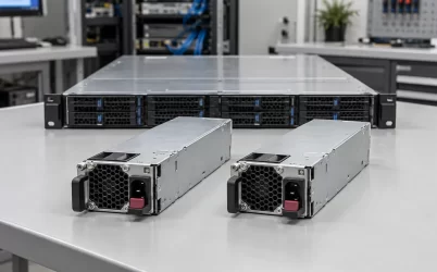
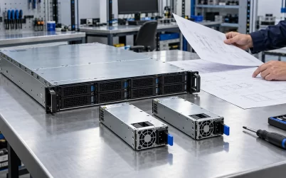
The CRPS3200T2 is listed as a 3200 W, 12 V Titanium CRPS module, but its published data does not establish that 3200 W is available at every input voltage and ambient temperature. The manufacturer lists four different main-output currents—98.4 A, 229.5 A, 245.9 A, and 262.3 A—without mapping them to operating conditions on the public product page. For a server design, the immediate task is to obtain that mapping and size the load against the applicable continuous rating. Treat the maximum figure as a conditional specification until the detailed technical manual identifies its input, temperature, airflow, and time limits.
The four current figures are operating points, not four simultaneous rails
The manufacturer listing identifies one main +12 V output and a +12 VSB / 3 A standby output. Its public listing appends four current values to the main output. The listing does not describe four independently available 12 V rails, nor does it assign each value to an AC or DC input band. Multiplying each listed current by nominal 12 V gives approximately 1181 W, 2754 W, 2951 W, and 3148 W. Those arithmetic results show why reading every number as a simultaneous full-power promise would be wrong; they do not themselves establish a usable power rating. Output-voltage tolerances, the allocation of standby power, and rating conventions could account for differences between a simple multiplication and the stated 3200 W class.
The 98.4 A figure is especially consequential. A platform drawing less than 3200 W at its peak can still exceed 98.4 A on the 12 V bus. If that lower current applies to the installation’s low-line input, the power design may need a higher-voltage feed, a different module, or a lower platform load. Conversely, assigning 98.4 A to low line without a manufacturer document would be an unsupported inference. The responsible interpretation is narrower: multiple current limits exist, their conditions are not explained in the public table, and the system rating cannot be finalized from that table alone.
Ask for the model-specific output-versus-input and output-versus-temperature curves, including whether the values are continuous or short-duration limits. Also ask whether the 3200 W label includes the standby output and which nominal output-voltage point was used to establish the current figures. A photograph of the exact nameplate can help identify a revision, but it should be reconciled with the matching manual rather than substituted for it.
Where the public specification is sufficient—and where it stops
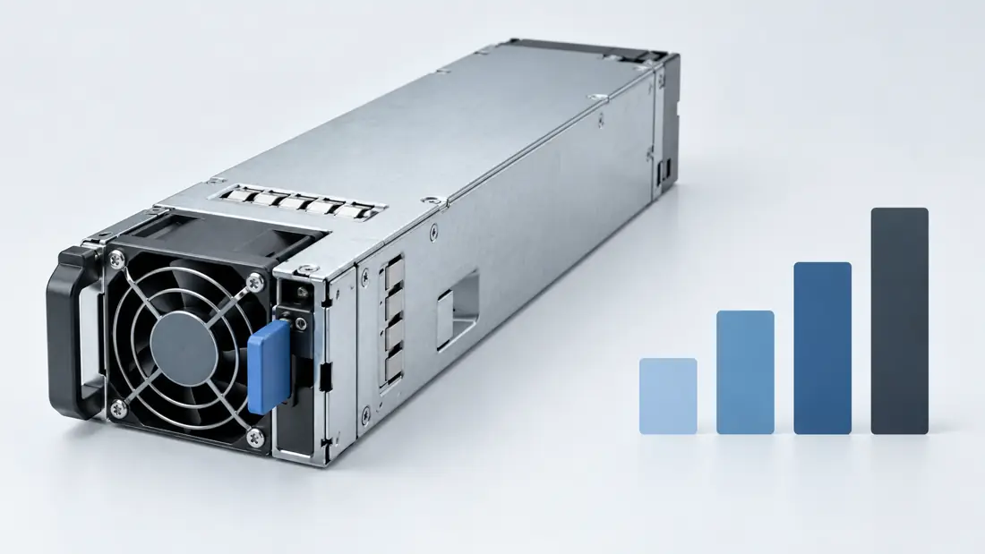
Several facts can be used immediately in a preliminary design. The listed input envelope is 90–264 VAC or 180–320 VDC. The module envelope is 185 × 73.5 × 40 mm, with FR airflow and a listed operating range of 0–55 °C. The efficiency designation is Titanium, and the standby rail is +12 VSB / 3 A. These values help narrow the mechanical bay, electrical architecture, and cooling arrangement. They do not prove full output across every point inside those envelopes. An input range says where the supply can operate; a maximum output label says what a rated condition can deliver. The missing relationship between the two matters most in a dense system.
For instance, a 200 V-class rack feed, a 120 V branch circuit, and a 240 V DC distribution system all sit within one of the listed input ranges, but they can impose different internal currents and losses. Without the model’s derating information, none should be declared equivalent for a 3200 W workload. The same distinction applies to the 55 °C figure. An operating-temperature limit does not tell the integrator whether nominal maximum output is continuous at 55 °C, whether inlet temperature is measured at the PSU face, or whether airflow has to meet a particular value.
Powernexu’s CRPS3200T2 product page is useful for identifying the model and its published headline data. It also reproduces the multiple current figures without their conditions. A technical manual for the exact hardware revision is therefore the governing document for a procurement specification. If the seller cannot provide one, the permissible load should remain an unresolved engineering item rather than a number inferred from neighboring models.
Build a current budget at the 12 V distribution boundary
A server’s power consumption is rarely presented in the same terms as a PSU’s output-current table. Processor, accelerator, memory, storage, fan, and conversion-stage specifications may be expressed as DC input, board power, thermal design power, or software-enforced caps. Translate them to the current that the common 12 V bus must actually deliver at the specified operating condition. Keep steady-state demand separate from short excursions, and identify which components share the same distribution path.
As an illustrative calculation, suppose a prospective system has a measured sustained 12 V load of 220 A and a brief 250 A operating excursion. At nominal 12 V these represent about 2640 W and 3000 W, respectively. Those are hypothetical system figures, not CRPS3200T2 ratings. The 220 A load is below three of the manufacturer’s listed current figures and above 98.4 A. Whether it is permissible therefore depends directly on which figure applies to the intended input and inlet temperature. The 250 A excursion additionally requires a documented transient allowance; the existence of a 262.3 A line item does not specify its duration, voltage regulation, or protection behavior.
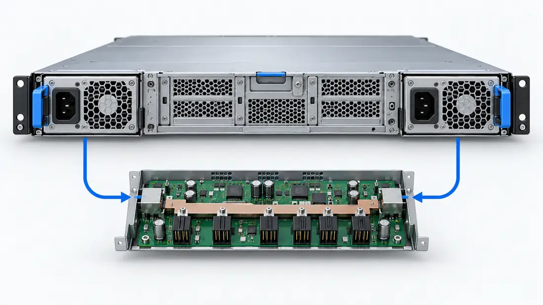
Work backward from the distribution board as well as forward from the PSU. A 12 V path at these currents involves busbars or PCB copper, blind-mate contacts, fusing, connectors, and downstream regulators. Their limits can be lower than the PSU’s nominal output. Voltage drop and I²R heating increase sharply with current, so a contact that is acceptable in a 1600 W build may be unsuitable here despite identical external module dimensions. The actual CRPS3200T2 mating interface and pin assignment are not established by the public listing. They must be checked against the chassis backplane drawing and the model-specific documentation.
Where loads sit on several board branches, a total current sum is insufficient for identifying the hottest connector or trace. Prepare a branch-level budget with each steady load, excursion, fuse, conductor, and contact path. This budget reveals whether the constraint is the module, one distribution branch, or the board’s common input. It also prevents a nominal 3200 W module from being treated as a substitute for a redesigned power distribution board.
Redundancy changes the usable 3200 W story
A two-module CRPS shelf can be wired for redundant operation, but redundancy is a property of the complete power path. If the intention is continued operation after one module is lost, the surviving module must carry the system’s required load under its own applicable input and thermal rating. Two 3200 W nameplates do not automatically make 6400 W of fault-tolerant capacity. A system operating above the single-module limit may have two working supplies during normal service yet lose the load when one is removed or fails.
For the hypothetical 220 A sustained example, a 1+1 arrangement requires each module to be approved to carry that current alone at the deployment condition. Sharing 110 A per module during normal operation is not the decisive test. The board’s ORing or isolation stage, current-share behavior, and control response affect the transfer when one input disappears. If the surviving module moves from 110 A toward 220 A faster than its output regulation can accommodate, the 12 V bus may dip even though the steady current is within an appropriate rating. The magnitude and duration of that transfer must be assessed with the actual platform, not borrowed from a generic CRPS description.
Power-source diversity introduces another limit. Two modules fed by the same branch circuit share a failure domain; modules fed by separate sources may still share a PDB and its single points of failure. The relevant design question is which interruption the platform must survive: loss of one PSU, one rack feed, one PDU, or a service action. The CRPS3200T2 output table alone answers none of those architecture questions. For a deeper treatment of board interfaces, Powernexu’s CRPS power distribution board article explains the adjacent design territory; the exact board must still be matched to this module.
FR airflow and the compact envelope constrain the bay design
The 185 × 73.5 × 40 mm dimensions make a preliminary fit check possible, but a blind-mate server bay needs more than an outer-envelope match. The insertion rails, latch, handle travel, AC inlet clearance, board connector position, and extraction space can vary across otherwise similar supplies. The public listing does not provide an integration drawing, so no drop-in compatibility should be assumed from the CRPS label or width alone. Before ordering a production quantity, compare the exact mechanical drawing and mating parts for the intended chassis.
The FR airflow designation is equally specific. It identifies the listed airflow direction for this model, not a selectable reverse-flow version. A chassis fan scheme that pushes against the module’s flow can raise inlet temperature or recirculate exhaust into the PSU bay. The result is a reduced thermal margin precisely when a high-current platform is most demanding. In a rack with hot rear exhaust and dense cabling, the local air entering a module may differ materially from a room sensor reading. Locate the temperature measurement where the supply actually takes in air.
At approximately 3 kW output, even high conversion efficiency leaves heat inside a narrow module. The Titanium designation is not a substitute for a load-specific efficiency curve, and it does not give an exact waste-heat value at the intended operating point. Measure or obtain that curve before sizing a thermal budget. Ensure that any removable module has an unobstructed inlet and outlet throughout service, and consider the neighboring module’s inlet condition when one bay is empty or blocked. A chassis test should exercise the most adverse credible fan state and inlet temperature, rather than relying on a favorable bench setup.
Evidence that closes the CRPS3200T2 rating question
A model-specific technical package should link each of the four listed 12 V current values to its exact condition. It should identify the continuous-output curve across input voltage and inlet temperature, the airflow requirement, and any short-duration overload allowance. It should define the usable 12 V voltage range, standby behavior, current sharing, status and control signals, connector pinout, protective responses, and the permitted hot-swap sequence. These are requests for evidence, not claims that every listed function exists in this model.
The next step is to compare that package with a measured platform load trace. Capture a representative sustained operating state, startup, accelerator transitions if applicable, and the highest expected fan demand. Then test the power path at the lowest planned input and the warmest credible PSU inlet condition. Monitor the 12 V bus at the load, not merely at the PSU, and inspect connector temperatures and module airflow. If redundancy is required, repeat the observation while a single module carries the load and during a controlled module-loss event under an approved service procedure.
These checks do not need to turn a product page into an exhaustive laboratory report. They answer one precise buying question: which published CRPS3200T2 current line applies to this installation, and does the server remain inside it during both normal and degraded operation? Until that relationship is documented, 3200 W should be treated as the model class and not as an unconditional capacity promise at the server’s particular input, inlet temperature, and distribution board.