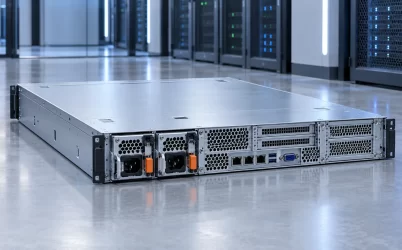
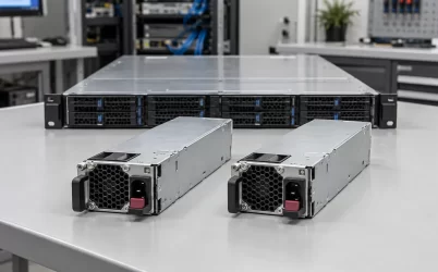
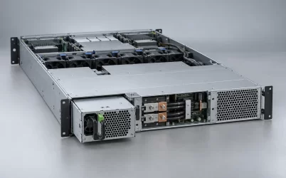
An HVDC server power supply accepts a high-voltage direct-current source and converts it to a lower-voltage bus usable by server electronics. The important distinction is where that conversion happens. Some platforms use a DC-input module in a conventional server PSU bay; others bring HVDC to a rack power shelf that produces a shared low-voltage distribution bus. A server built for an AC-input module does not become HVDC-compatible because a rack has a DC feed. The source, converter, mating interface, protection, and host all have to belong to the same architecture.
The term HVDC describes a source boundary, not one universal PSU
In a data-center discussion, “high-voltage DC” may refer to a facility distribution bus, a rack feed, or the input of a removable converter. It does not specify one voltage, connector, output rail, or power level. The phrase is also used in utility transmission for much higher voltages, so the intended equipment boundary matters. For server purchasing, ask where the DC is delivered, where it is converted, and what voltage finally reaches the server load. Those three locations define different products and safety responsibilities.
One arrangement puts an HVDC-capable PSU at each server. The incoming DC enters its approved input interface; the module converts it to the host’s required output, such as a documented 12 V bus. In another arrangement, a rack shelf receives HVDC and produces a lower-voltage shared bus, commonly associated with rack-level distribution in open hardware architectures. Server nodes then receive that bus through their own distribution and point-of-load stages. The shelf supply is not a drop-in replacement for a small server module merely because both convert DC.
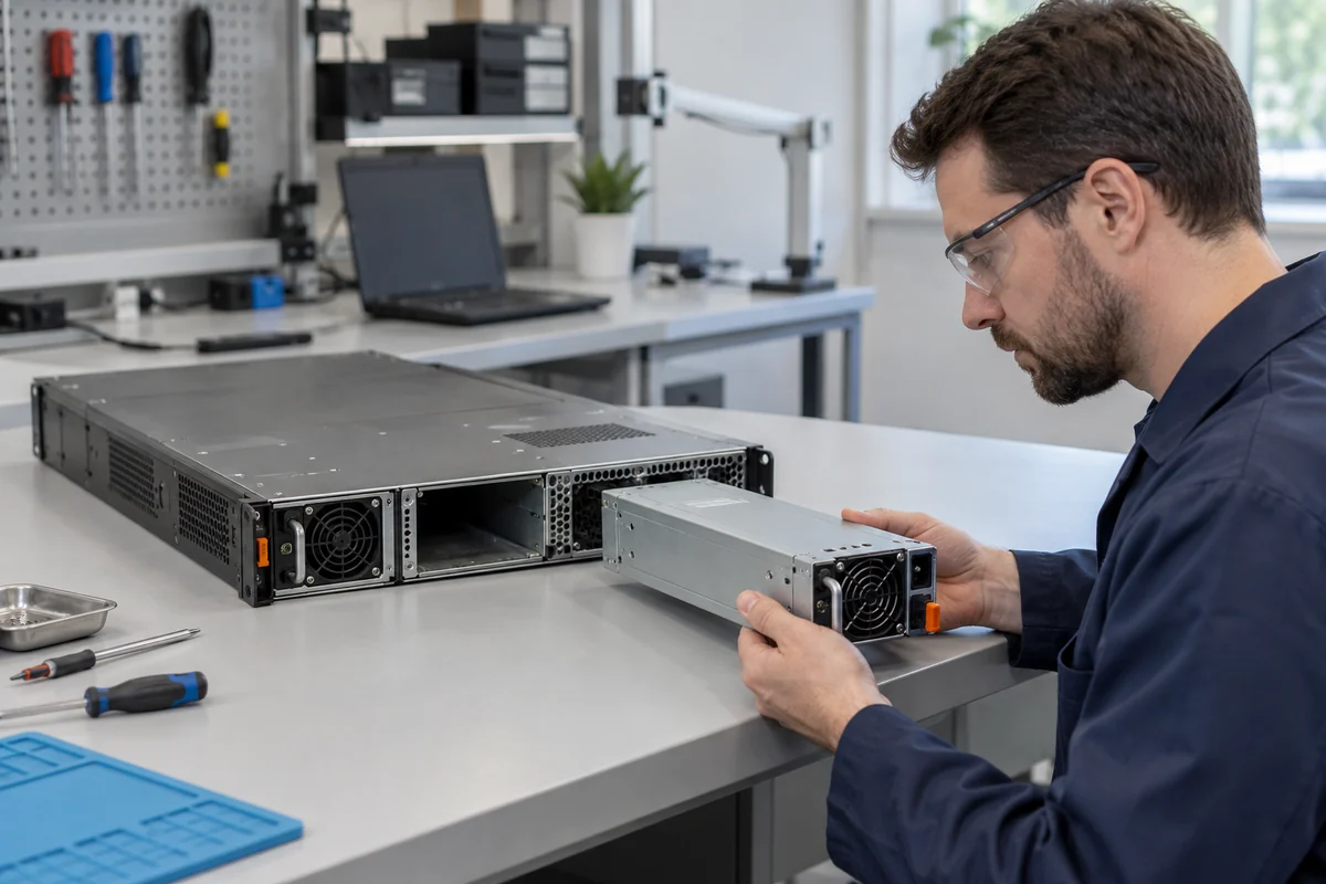
The Open Compute Project’s Open Rack HVDC-to-LVDC PSU specification is a concrete example of the second architecture: it describes an HVDC-input module intended for a rack power shelf and a lower-voltage output for rack loads. That specification is evidence for its defined design, not a declaration that every HVDC server supply uses the same input or output. Its details should not be copied onto an unrelated CRPS module or a proprietary server.
A useful drawing places four boxes in order: DC source, distribution and protection, HVDC-input converter, and server load. If the converter is inside the server, the high-voltage cable, contact arrangement, and service boundary reach the server bay. If conversion is in the rack shelf, the server connection is a lower-voltage bus and the shelf carries the HVDC interface. The location of the converter determines who owns a given failure, spare, and maintenance procedure.
Input envelope and polarity come before the output-wattage claim
“DC input” on a specification is incomplete unless it names the allowed input window and the physical polarity arrangement. A converter designed for one HVDC bus can refuse to start, derate, trip, or be damaged if connected to another. Even two sources described by a similar nominal number may differ in normal regulation, battery float behavior, transient excursions, return arrangement, and startup sequence. A DC-input module should be matched to the actual source envelope, including credible high and low conditions, not only the label on a distribution cabinet.
DC also changes the input-switching problem. Unlike AC, it does not pass through a zero crossing every half-cycle. Connectors, disconnects, fuses, contactors, and service procedures must be suitable for the specified DC voltage and prospective fault current. A connector that mechanically mates or has an acceptable AC rating is not thereby qualified for HVDC interruption. The cabinet protection scheme must isolate a fault without turning one module failure into loss of the entire shared bus. Such details belong to the system’s approved design and local electrical requirements, not a generic blog pinout.
For a specific product example, Powernexu lists the CRPSHD1600D2 server power supply with an 180–400 VDC input range as well as an AC input range. That published range makes it relevant to a defined class of high-voltage DC sources; it does not establish compatibility with every DC rack, chassis, or server PDB. An integrator still needs the exact host interface, input protection arrangement, and supported operating configuration. Nor should a supply whose listed DC maximum is 400 V be assumed suitable for an 800 V distribution scheme.
The same caution applies to terminology such as “dual input.” AC and DC entries in one model’s specification do not imply that both may be connected simultaneously, automatically transferred without interruption, or combined. Those behaviors require explicit product and platform documentation. Where the design calls for A/B DC feeds, determine whether the redundancy is at the facility source, the converter module, or both. Two connector locations alone do not establish independent failure domains.
Power flows through several protection and conversion stages
At the rack or server inlet, the converter must tolerate the documented source while protecting itself and the distribution system. Depending on the architecture, this can involve input filtering, inrush control, undervoltage and overvoltage response, and a defined path for a fault. The downstream converter then regulates the low-voltage output. The server still has board-level regulators close to CPUs, GPUs, memory, and other loads. Calling the entire path an “HVDC PSU” hides these distinct functions and can obscure where a loss occurred.
Conductor current follows the simple relationship between power and voltage. At a fixed delivered power, a higher distribution voltage means lower current before conversion, which can reduce conductor cross-section or resistive loss for a given route and design. That is one reason higher-voltage distribution is considered for dense racks. It does not mean the installation becomes automatically smaller or more efficient. Insulation, spacing, connectors, interruption devices, protection coordination, conversion stages, and operating safety may impose their own size and loss penalties. The complete architecture, rather than a single cable, determines the result.
Consider a hypothetical 10 kW transfer before conversion. Ignoring losses, 10 kW at 400 V corresponds to 25 A, whereas 10 kW at 50 V corresponds to 200 A. The arithmetic explains why architects may move the longer distribution path to the higher-voltage side and convert near the rack loads. It is not a cable-sizing recommendation. Real installations must account for allowable current, fault duty, voltage drop, insulation, thermal environment, redundancy, and the actual bus voltage under operation.
Where a rack power shelf is used, multiple modules may share a low-voltage output bus. Failure isolation, output ORing or equivalent control, and current sharing then become shelf-level concerns. Where each server has its own HVDC-input module, the server backplane or PDB may combine redundant outputs. The two designs place the common bus and replacement operation in different places. Maintenance teams should know which module can be withdrawn, what remains energized, and which loads are protected by the surviving path.
HVDC distribution shifts the service and safety boundary
A high-voltage DC feed reaching a server or rack shelf requires a controlled service boundary. Personnel need a defined method to isolate the source, verify the disconnected state, and work within equipment-specific procedures. Capacitors may retain energy after the supply is isolated. An unplugged module, an opened shelf, and a powered distribution rail are not equivalent conditions. The existence of hot-swappable hardware does not authorize live access to every upstream component.
Protection design also needs to address the direction and magnitude of possible fault current. A battery-backed DC source can sustain a fault differently from an AC branch protected by familiar downstream devices. Multiple feeds may back-feed a common point unless isolation is designed and verified. Equipment grounding or bonding must follow the actual system architecture; “DC” does not mean the enclosure can float casually or that protective conductors are optional. These are application-specific electrical design issues requiring qualified review, not settings inferred from a PSU marketing page.
Thermal service conditions matter in a less obvious way. A high-voltage input can reduce upstream current, yet the conversion losses still emerge as heat where the converter sits. Moving conversion into a rack shelf concentrates that heat and fan maintenance at the shelf. Keeping conversion in every server spreads the loss across server airflow paths. Neither arrangement is automatically cooler. Fan failure behavior, exhaust direction, density, and replacement access determine how the physical rack handles the loss.
Monitoring boundaries differ too. A server’s management controller may see the local PSU’s output and status, while a rack shelf has its own power-management interface. The existence of telemetry at one layer does not guarantee visibility into upstream DC feeder faults or battery state. An operations dashboard should distinguish a failed converter, a feed that has disappeared, and a low-voltage output fault; otherwise a technician can replace the wrong module while the source problem remains.
Choose between server-level and shelf-level conversion by failure domain
A DC-input module in a server bay can suit a platform expressly built and approved for that source. It keeps the conversion function close to one host and may align with existing per-server spare and management practices. Its limitation is that every server receiving HVDC needs a compatible high-voltage input path and service arrangement. If the rack already contains conventional AC-only servers, replacing the building feed does not solve their input incompatibility.
A rack shelf can centralize HVDC conversion and distribute a lower-voltage bus to a family of designed-for-rack loads. That can reduce the number of high-voltage terminations at individual nodes, but introduces a shared distribution and shelf failure domain that must be managed. The shelf, busbar, protection, node connectors, and orchestration belong to the same architecture. A node designed for that low-voltage rack bus is not automatically compatible with a conventional server backplane, even if both ultimately power similar processors.
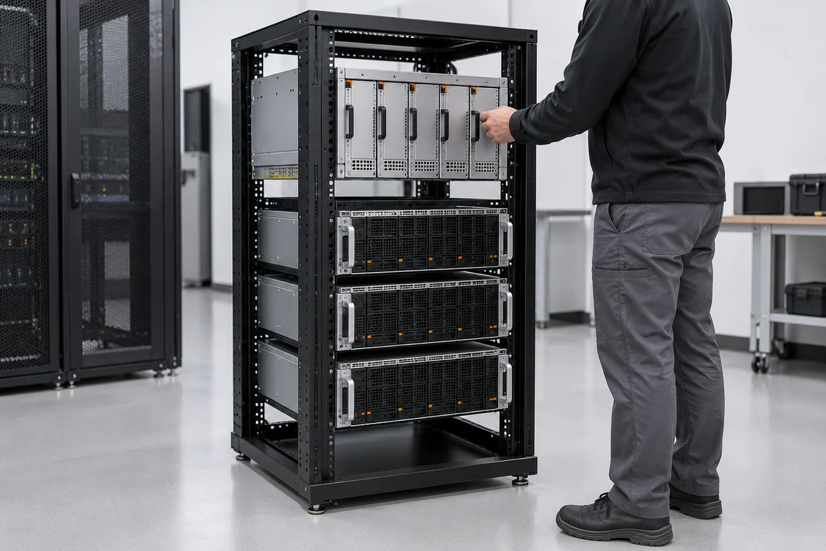
A useful comparison begins with the physical asset that may fail. In per-server conversion, loss of one converter may affect its host, subject to that host’s redundancy arrangement. In shelf conversion, loss of one module may be covered by other shelf modules, but a shelf bus or upstream feed can affect more nodes. The number of modules alone does not define availability. The remaining capacity, distribution isolation, and independence of A/B sources show whether the desired service survives a single failure.
The strongest economic claim for HVDC should also be system-specific. Removing one conversion stage or lowering distribution current can create a benefit, but an additional DC-DC stage, protection hardware, or unusual service process can offset some of it. Compare AC input to delivered DC load across the actual equipment boundary, not one peak-efficiency figure from a converter datasheet. Include the portion of time spent at light load, because a shelf with many modules can operate at a different fraction of rating than a server-local module.
What an HVDC-capable server PSU actually proves
An HVDC input specification proves that a named product is designed to operate over its documented DC input conditions. It does not prove that the surrounding rack is protected correctly, that a particular host accepts its outputs and signals, or that a facility can safely replace its AC feed with DC. The decisive match is between the actual source envelope, the converter’s input and output interfaces, and the intended server or shelf platform.
For a conventional server looking toward DC infrastructure, the practical question is whether an approved DC-input module exists for that exact server and whether its source, bay, PDB, firmware, and redundancy behavior are documented together. For a new high-density rack, the question may instead be whether a shelf-based conversion architecture provides the required low-voltage bus and fault containment. Treating those as two distinct designs prevents a high-voltage distribution label from masquerading as a universal server-PSU compatibility statement.