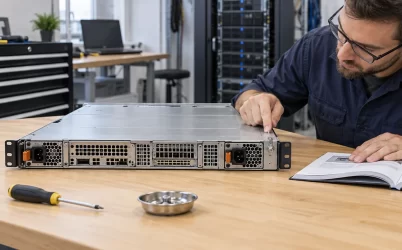
CRPS3200TS5 is a 3200 W class, Titanium-rated CRPS module with a +54 V main output and a separate +12 VSB / 2 A standby output. It belongs in a server designed to distribute 54 V and convert it near the loads; it is not a direct replacement for a 12 V CRPS module merely because the power rating and 185 × 73.5 × 40 mm envelope look familiar. The published +54 V current figures—24 A, 48.2 A, 54 A, and 59.3 A—also describe different operating limits, not four rails that can be combined. For a 54 V platform, the immediate questions are where conversion occurs, which input conditions permit the required power, and whether the mating distribution hardware is built for this rail.
A 54 V module changes the distribution boundary
In a conventional 12 V server, the CRPS output often enters a distribution board that routes high-current 12 V paths to downstream regulators. CRPS3200TS5 moves the principal distribution voltage to 54 V. The downstream board must therefore accept 54 V and provide the conversions required by processors, accelerators, memory, storage, fans, and other loads. A 12 V board connected to the wrong main rail could expose components to a voltage far beyond their input ratings. Similar mechanical dimensions do not remove that electrical mismatch.
The practical attraction of 54 V is lower distribution current at a given power. A hypothetical 2700 W delivered at 54 V corresponds to 50 A before distribution losses; at 12 V, the same power corresponds to 225 A. These are circuit-level arithmetic examples, not CRPS3200TS5 ratings at a particular line voltage. Lower current can ease conductor, connector, and board-trace loss because resistive heating rises with current squared for the same resistance. Yet the required point-of-load converters add their own losses, space, control, and thermal needs. The whole path from AC input to the device rail determines whether a 54 V design is advantageous.
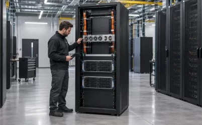
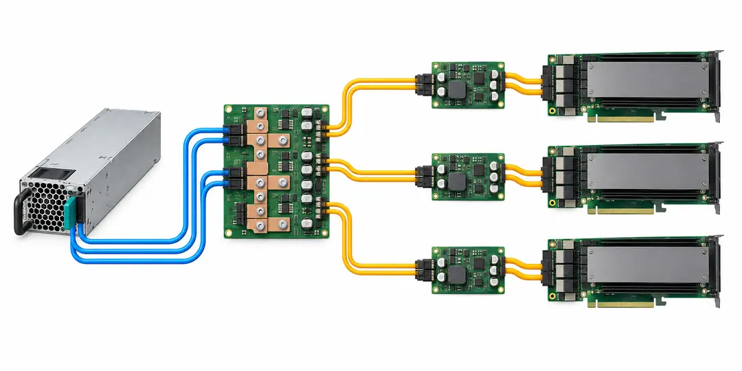
That distinction is useful when a GPU server’s power is distributed over a backplane or across several accelerator trays. The higher-voltage bus may travel farther through the chassis, while short local conversion paths provide the low-voltage rails. This is an architectural option, not evidence that a particular GPU card accepts 54 V directly. Its specified input, carrier board, cable assembly, and local regulators still define the connection.
The CRPS3200TS5 product page identifies the main and standby rails, mechanical envelope, input range, airflow direction, and operating temperature. Those headline values establish a starting point. They do not by themselves specify a compatible PDB, connector mating part, output sequencing, remote-sense arrangement, or the approved operating point of a finished server.
Read the current values against the available input
Powernexu’s listing gives four +54 V current values: 24 A, 48.2 A, 54 A, and 59.3 A. A published CRPS3200TS5 selection sheet provides additional context for several of them: 24 A at 100–127 Vac, 54 A at 200–220 Vac, and 59.3 A at 220–240 Vac or 240 Vdc. The manufacturer’s broader public listing includes 48.2 A but does not explain that figure’s exact condition. These sources are useful for screening; a revision-controlled datasheet from the actual supplier should settle the allowable operating envelope for a purchase.
The current values make an important facility-power distinction visible. At 54 V nominal, 24 A is about 1.30 kW and 59.3 A is about 3.20 kW. The 3200 W nameplate must not be assumed available from every receptacle in a wide 90–264 Vac input range. A rack powered at low line may run the module at a substantially lower permitted output than a high-line rack. The server’s startup, steady operation, and degraded-mode demand all need to fit the applicable input-specific limit.
There is also a gap between a nominal multiplication and a warranted power figure. Real output voltage can vary within a specified tolerance, the standby output contributes to power accounting, and a listing may round the nameplate. Multiplying 54 by a published current is a useful sanity check, not a substitute for the product’s exact combined-output and input-derating rules. The 48.2 A point especially deserves direct clarification: assigning it to an input band by analogy with another model would be an invented specification.
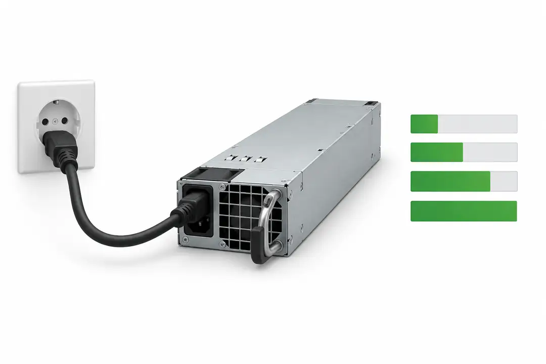
A sensible load plan starts with the actual branch-circuit and PDU voltage at the server, including any tolerated low-voltage condition. Compare that voltage with the supplier’s output envelope, then consider the rack’s fault and maintenance scenarios. If a site may be operated from both low-line and high-line feeds, the lower permitted capacity may govern the entire service design unless load shedding is explicitly engineered.
Follow the 54 V path through the server
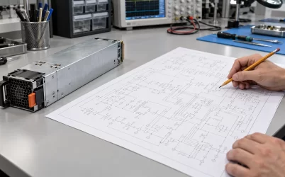
The connection between a CRPS3200TS5 bay and the first 54 V distribution node is an electrical and mechanical interface. It needs the correct mating connector, polarity, contact arrangement, insertion geometry, ground path, isolation, and board rating. A connector that physically engages is not proof that its signal pins or power contacts have the same assignment as another CRPS product. The exact hardware revision and backplane drawing should agree before a module is energized.
At the distribution board, the current may split among several converter branches. Each branch should be protected and monitored according to the platform’s design. The 54 V bus voltage must remain within the input range of every downstream converter during startup, load transitions, steady load, shutdown, and a PSU fault. Cable assemblies and copper planes are sized for the actual current and temperature rise, not for a marketing description such as “3200 W compatible.” Contact resistance can become a significant heat source where high current is concentrated in a compact connector, even though the bus current is lower than a 12 V equivalent.
The +12 VSB / 2 A output serves a different purpose from the +54 V power path. In many server architectures a standby rail supports management and power-control circuitry while the main output is disabled; the exact CRPS3200TS5 control sequence must come from its technical manual. Treating the standby output as a general 12 V server rail would exceed what the published two-ampere figure supports. Conversely, omitting standby provisioning can leave the management controller unable to request or supervise main power.
For an accelerator platform, the conversion layout matters as much as the source rating. A converter next to a high-current GPU domain can shorten its low-voltage path, but it also concentrates heat near expensive devices and may introduce switching noise. Place those converters using board-level thermal and signal-integrity analysis. The CRPS module rating does not establish GPU transient performance at the final device rail; that behavior includes the intermediate bus, the local converter, bulk capacitance, control loop, and distribution impedance.
Redundant capacity is set by the surviving 54 V path
CRPS modules are often used in redundant bays, but two 3200 W nameplates do not automatically make 6400 W of continuously usable redundant capacity. In a two-module 1+1 arrangement, the full server load must remain within the capability of one surviving module at the actual input condition if continuity after a module failure is required. If each module is only permitted to supply 24 A on low-line input, a planned 50 A bus load does not meet that one-module survival test. The platform could operate while both modules share the demand and still fail its intended redundancy objective.
The same reasoning extends beyond the module. A shared 54 V distribution board, common conversion stage, or single AC branch can defeat an otherwise redundant module arrangement. Current sharing and fault isolation should be documented for the particular chassis. A supplier’s statement that a CRPS family supports redundancy does not establish the number of modules, permitted loading, or response to one failed source in this system. The design must define whether it is protecting against removal of one module, an AC feed loss, a PDU failure, or another event.
Hot-plug service raises a separate question: what happens electrically as a module is removed or inserted? The surviving path should carry the load, while the incoming unit connects through a controlled sequence that avoids excessive bus disturbance or inrush. The published selection sheet describes hot-pluggable operation and current sharing, but a live-replacement procedure still needs the chassis and PDB implementation. A technician should not infer safe service under full load from the module label alone.
For a detailed discussion of the board side of this interface, Powernexu’s CRPS power distribution board article explains how the board relates to redundant modules. CRPS3200TS5 needs a board designed for its 54 V path and verified connector and control signals; a generic board description does not confirm a specific match.
The compact bay trades space for concentrated heat
The listed enclosure measures 185 × 73.5 × 40 mm, and the public product data describes FR airflow and a 0–55 °C operating range. That small package can fit a dense server bay, but the full-size power envelope places considerable conversion heat in a narrow airflow path. Airflow direction must agree with the chassis fan arrangement and with neighboring modules; opposed flows can recycle warm exhaust into an intake. The relevant temperature is the condition at the PSU intake and within the specified installation environment, not merely the room thermostat.
A Titanium efficiency label indicates an efficiency class, not a fixed percentage at every input and load. Higher efficiency can reduce heat compared with a less efficient alternative under comparable conditions, yet the amount depends on the curve and operating point. Server designers should obtain the applicable efficiency data if power and cooling economics are being calculated. It would be misleading to apply a single assumed percentage to the rack’s entire annual load without considering idle time, redundant sharing, and the downstream 54 V converters.
Evidence to request before committing to a 54 V platform
A buyer who has the exact CRPS3200TS5 part number still needs an integration package. The first document is a revision-controlled output table showing the permissible +54 V current at each intended AC or DC input condition, including the unexplained 48.2 A point and any temperature derating. Obtain the combined main-plus-standby power rule and the allowable operating environment as well. If the intended feed is high-voltage DC, confirm the supported range and connector/safety implementation for the supplied revision rather than extrapolating from the broad site range.
The second document is the matching mechanical and electrical interface: connector drawing, pin functions, mating-part identification, chassis retention, airflow orientation, and extraction clearance. A third is the system-level behavior specification—main output enable, power-good timing, standby availability, telemetry, sharing, and fault response—where those functions are used by the host. Public family material may describe PMBus compliance, but the exact registers and integration behavior require the correct technical documentation. Do not copy a pinout or software profile from a visually similar 12 V module.
Finally, map the 54 V distribution path to the actual loads. The PDB, converters, protection devices, cables, and connectors should have ratings for both continuous operation and relevant transients. In a redundant system, document the load that remains after one module or feed is unavailable. In a dense accelerator server, exercise representative startup and load changes while measuring at the 54 V board and the final device rails. These are system-design tasks, not claims that any particular server has already passed them.
CRPS3200TS5 is most naturally considered where a server already uses, or is intentionally being designed around, a 54 V intermediate bus. Its published size and 3200 W class are useful screening facts; the distinguishing engineering choice is where power is converted and how that 54 V path remains within its verified envelope. If the host is a 12 V platform with no 54 V distribution and conversion stage, choosing a 12 V supply architecture is the direct starting point rather than treating this module as a wattage-equivalent swap.