A screw can pass through an open-frame power supply’s mounting hole yet still be unsuitable: its washer may extend beyond the permitted contact area, or its tip may reach the bottom of a spacer before the board is clamped. To mount an open frame power supply, use its designated fixing points and documented hardware arrangement inside a suitable protective enclosure. Resolve the assembled screw, washer, PCB, spacer, and mounting-panel geometry before tightening anything. This walkthrough focuses on that attachment: how to translate an installation drawing into hardware that supports the board while preserving the manufacturer’s electrical and mechanical constraints.
Draw the attachment through the mounting hole
Start with the exact supply’s mechanical drawing and installation instructions, including the applicable revision. A board outline and hole coordinates describe location, but may leave spacer requirements, conductive contacts, underside components, and tightening instructions in separate notes. Bring those details into the same working view. No exact-model installation drawing accompanies this article, so the dimensions used later are hypothetical teaching inputs.
Draw a section through one proposed fixing. For a screw entering a female-threaded spacer from above, the sequence might be screw head, captive washer assembly, PCB, spacer, and mounting panel. Another construction could use a through-bolt and nut or a male-threaded support. These arrangements have different length relationships. Select the actual attachment geometry before calculating engagement or ordering fasteners.
Mark the surfaces that carry the clamp load. The washer bears on a permitted area above the PCB; the spacer supports an allowed area underneath. Their footprints need to remain within the mounting provisions. A narrow support under a much larger washer can leave part of the board locally unsupported. Whether that arrangement is acceptable requires the board’s instructions and mechanical assessment, rather than an assumption based on the hole diameter.
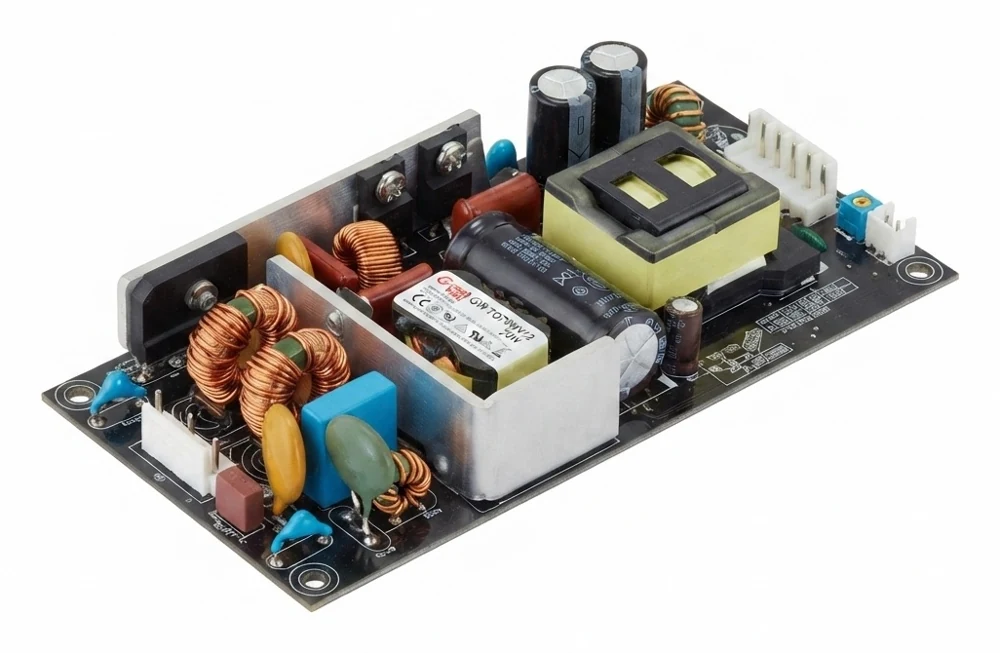
The underside drawing deserves its own attention. Solder joints and surface-mounted components can project below the PCB. Spacer height establishes the board’s position above the panel, but the remaining gap depends on those projections and nearby panel features. A rib, insert, screw, or raised boss can become the nearest surface. Measure each relationship from a clearly identified datum.
COSEL’s installation guidance connects spacer length to the insulation distance identified in each product catalog and separately addresses underside component height. Those are different constraints: preventing physical contact does not establish adequate electrical separation. Its discussion of insulating material is conditional guidance, not blanket permission to reduce spacer height. Carry the selected board’s actual requirements into the section view, including required conductive contacts at identified holes.
Compare the washer and spacer footprints before the thread
A SEMS screw combines a screw with one or more captive washers. That assembly description does not establish its outer envelope. Different washer forms can accompany screws with the same nominal thread, producing different bearing diameters and assembled heights. A purchasing description that names only the thread therefore leaves important geometry unspecified.
COSEL’s open-frame installation article explicitly distinguishes washer sizes associated with older JIS and ISO arrangements, including different size categories within the standards. In that guidance, COSEL recommends ISO small SEMS hardware associated with a 6 mm washer outside diameter and metal spacers no larger than 6 mm outside diameter. These recommendations belong to COSEL’s described mounting provisions; they are not universal dimensions for open-frame power supplies.
The useful general lesson is to compare the actual fastener drawing with the permitted mounting region. Include the screw head as well as the washer. A smaller washer does not solve an interference if the head remains too wide or approaches a nearby component above the board. Where a captive washer can move relative to the screw, consider its permitted displaced position rather than assuming perfect concentricity.
For a purely hypothetical circular mounting area 7.0 mm across, a centered 6.0 mm washer leaves 0.5 mm of radial geometric allowance. A centered 7.0 mm washer leaves none. Neither result establishes electrical clearance or acceptable loading. The example simply shows why equal screw threads can produce different fits, and why hole location, washer movement, and manufacturing variation matter when the available area is small.
Apply the same footprint comparison below the board. A spacer’s hexagonal body, flange, or shoulder can occupy more space than its nominal thread suggests. Compare its largest relevant outline with underside keep-outs and nearby components. A circular outside diameter cannot adequately describe a flanged or noncircular support.
Material is another controlled feature. At a mounting point requiring conductive contact, replacing a specified metal spacer with resin changes the electrical arrangement. COSEL notes that its FG-marked holes have an underside conductive pattern and recommends metal spacers there. The mechanical footprint and intended electrical contact must both survive a hardware substitution; matching dimensions alone does not preserve both functions.
Calculate screw reach from the assembled bearing surfaces
Screw length becomes meaningful once its reference surface and the clamped layers are known. For the hypothetical geometry here, use a screw whose supplier drawing measures length from beneath the head. It passes through a washer assembly and PCB into a blind female-threaded spacer. The spacer top directly supports the PCB underside. This description deliberately excludes countersunk heads and other length conventions.
The distance remaining below the PCB equals screw length minus the assembled washer thickness and PCB thickness. Call that distance screw reach into the spacer. Reach is a geometric quantity. It does not automatically equal effective thread engagement, because entry chamfers, incomplete threads, and the screw’s end form can reduce the length actually carrying load.
Assume a hypothetical screw length of 6.0 mm, an assembled washer thickness of 0.8 mm, and a PCB thickness of 1.6 mm. Nominal reach is 6.0 − 0.8 − 1.6 = 3.6 mm. Every dimension in this example is invented. No minimum engagement, permitted torque, or approved mounting arrangement is assigned to a commercial PSU.
Now include variation. Suppose screw length is 6.0 ± 0.2 mm, washer thickness is 0.8 ± 0.1 mm, and PCB thickness is 1.6 ± 0.15 mm. Treat these as stipulated limits and combine their extremes conservatively. The resulting interval describes possible geometric reach under those assumptions, without assigning a probability to either endpoint.
| Stack condition | Calculation | Reach |
|---|---|---|
| Shortest reach | 5.8 − 0.9 − 1.75 mm | 3.15 mm |
| Nominal reach | 6.0 − 0.8 − 1.6 mm | 3.60 mm |
| Longest reach | 6.2 − 0.7 − 1.45 mm | 4.05 mm |
Suppose the spacer supplier additionally guarantees at least 4.0 mm from its top bearing face to the blind-hole bottom. The longest calculated reach exceeds that depth by 0.05 mm. This combination does not establish freedom from bottoming across the stipulated limits, even though its nominal dimensions appear to fit. No universal bottom clearance is implied; any required allowance must also be included.
A screw that contacts the blind-hole bottom can resist further rotation without producing the intended clamp at the board. Tightening harder does not correct excessive reach. A supported shorter screw, different spacer, or revised approved stack may resolve the geometry, but each change also affects engagement, bearing position, or installed height. Recalculate the changed relationship rather than selecting a remedy by appearance.
The opposite extreme needs separate evidence. A 3.15 mm minimum reach cannot establish sufficient engagement without the screw and spacer specifications, thread details, materials, and required joint performance. Comparing reach with a minimum engagement requirement also requires accounting for unusable thread lengths. A drill depth and a full-thread depth describe different features.
A through-fastened arrangement needs a different section. The calculation may include the panel, a nut, and additional washers, while projecting thread must remain clear of nearby parts. Increasing spacer height does not increase screw reach into a top-mounted female thread when the upper clamped layers remain unchanged. It changes board elevation; those two effects should remain distinct.
Let the supports establish position before tightening
With radial envelopes and axial reach resolved, place the board on its intended supports without using the screws to pull it into position. Perform assembly with power isolated and stored energy addressed under the equipment’s service procedure. The board should approach its intended support plane without a component touching the panel or a connector becoming an unintended prop.
Several individually suitable spacers can still produce an unsuitable assembly. Their heights, seating surfaces, and panel flatness determine the combined support plane. A burr beneath one spacer or a distorted panel can raise one corner. Drawing that corner down with a screw imposes a different board shape from the one presented by the free assembly.
Investigate a rocking board before applying final torque. The cause could be unequal supports, debris, underside interference, or board flatness outside the permitted condition. An extra washer beneath one corner may appear to stop the rocking while changing installed height and electrical contact. Any correction needs to belong to the documented mounting arrangement.
Hole alignment has a similar distinction. Clearance between a screw and PCB hole can accommodate some positional variation, but that allowance is finite. Multiple supports must fit the board’s hole pattern together. If one screw enters only after another fixing is forced sideways, tightening is being used to correct location. Resolve the panel pattern, support position, or applicable tolerances instead of enlarging the PSU’s mounting holes.
Use the manufacturer’s fastening method and applicable torque instruction where provided. A torque value borrowed from a generic screw table does not establish an acceptable clamp load for the PCB joint. Washer configuration, thread condition, support material, and bearing surfaces affect the result. Thread-locking materials and replacement locking washers likewise require assessment against the intended assembly.
Once secured, the board should retain its intended position when the connectors and restrained harnesses are installed. Cable insertion force or an unsupported cable bend can load the PCB after an apparently satisfactory mechanical assembly. Arrange the host’s cable retention so the mounting joint is not asked to compensate for an imposed wiring misalignment.
XP Power’s installation guidance also identifies enclosure spacing, specified ground connections, and installed cooling as constraints on mounting. A mechanically satisfactory stack does not settle those wider responsibilities. Powernexu’s discussion of embedding an AC-DC open-frame supply safely addresses that broader integration task. Here, retain those requirements as limits on the hardware geometry rather than repeating an enclosure design procedure.
The mounting drawing can now identify an actual hardware set: screw ordering reference and length convention, captive washer configuration, spacer geometry and material, permitted contact surfaces, and the assembly instruction. Attach the dimensional comparison to that set. Where manufacturer information is missing, name the unresolved feature precisely, such as the permitted bearing diameter or minimum effective engagement, instead of filling it with a customary value.
This detail matters when a replacement screw arrives. A substitute with the same thread and nominal length can have a thicker captive washer stack, reducing reach, or a wider head, increasing interference. A thinner washer can increase reach toward a blind-hole bottom. The mounting arrangement remains reproducible when its bearing surfaces and dimensional limits travel with the hardware identity, so a seemingly equivalent fastener does not quietly change how the power board is held.