Class I and Class II industrial power supplies use different approaches to protection against electric shock. Class I combines insulation with protective earthing; Class II relies on double or reinforced insulation without relying on protective earth for that protection. Neither label, by itself, establishes the safety classification of the machine containing the supply. For an industrial equipment builder, the useful comparison is how the converter’s documented protection arrangement continues through its mounting, enclosure, wiring, and accessible parts.
The distinction also has nothing to do with choosing a higher performance tier. Class II is not an upgrade number, and it is not NEC Class 2. A candidate can have a suitable output voltage yet require an installation arrangement that the intended equipment cannot provide. Understanding that boundary makes the comparison more useful than counting input terminals or choosing by enclosure material.
Class I and Class II protect the person through different arrangements
In a Class I arrangement, protective earthing participates in the shock-protection system. Basic insulation separates hazardous live circuits from conductive parts assigned to the protective arrangement, while the protective conductor provides the intended fault-current path. The construction and protective devices must work together under the applicable equipment requirements. A wire carrying an earth symbol is therefore part of a defined protective system, rather than an optional noise accessory.
Class II protection instead uses double or reinforced insulation. Double insulation combines basic and supplementary insulation; reinforced insulation provides the corresponding protective function through an insulation system assessed for that purpose. Reinforced does not mean a purchaser should expect to see two separate sheets in a photograph. Transformer construction, component selection, board layout, barriers, and distances can participate in the evaluated arrangement.
This difference does not mean a Class I converter has basic insulation at every boundary. Its input-to-output barrier may use reinforced insulation while another boundary uses basic insulation with protective earthing. Conversely, identifying one reinforced barrier inside a converter does not establish that every accessible surface of the completed machine has Class II protection. The relevant question names both sides of each barrier.
Neither class promises better efficiency, lower output ripple, longer service life, or greater output capacity. Those are separate model specifications. The meaningful trade-off concerns the protection architecture that the equipment builder can implement and maintain. Class I preserves a protective conductor dependency; Class II places the corresponding burden on the insulation arrangement and its continued integrity throughout the accessible assembly.
The component label stops at its assessed boundary
An external enclosed power supply and an open-frame converter can carry similar class language while delivering different integration responsibilities. An external unit may provide its own assessed enclosure and mains connection. A board intended for building into equipment leaves surrounding accessibility, mounting, and enclosure relationships to the host design. The phrase suitable for Class II installation must be read with those conditions.
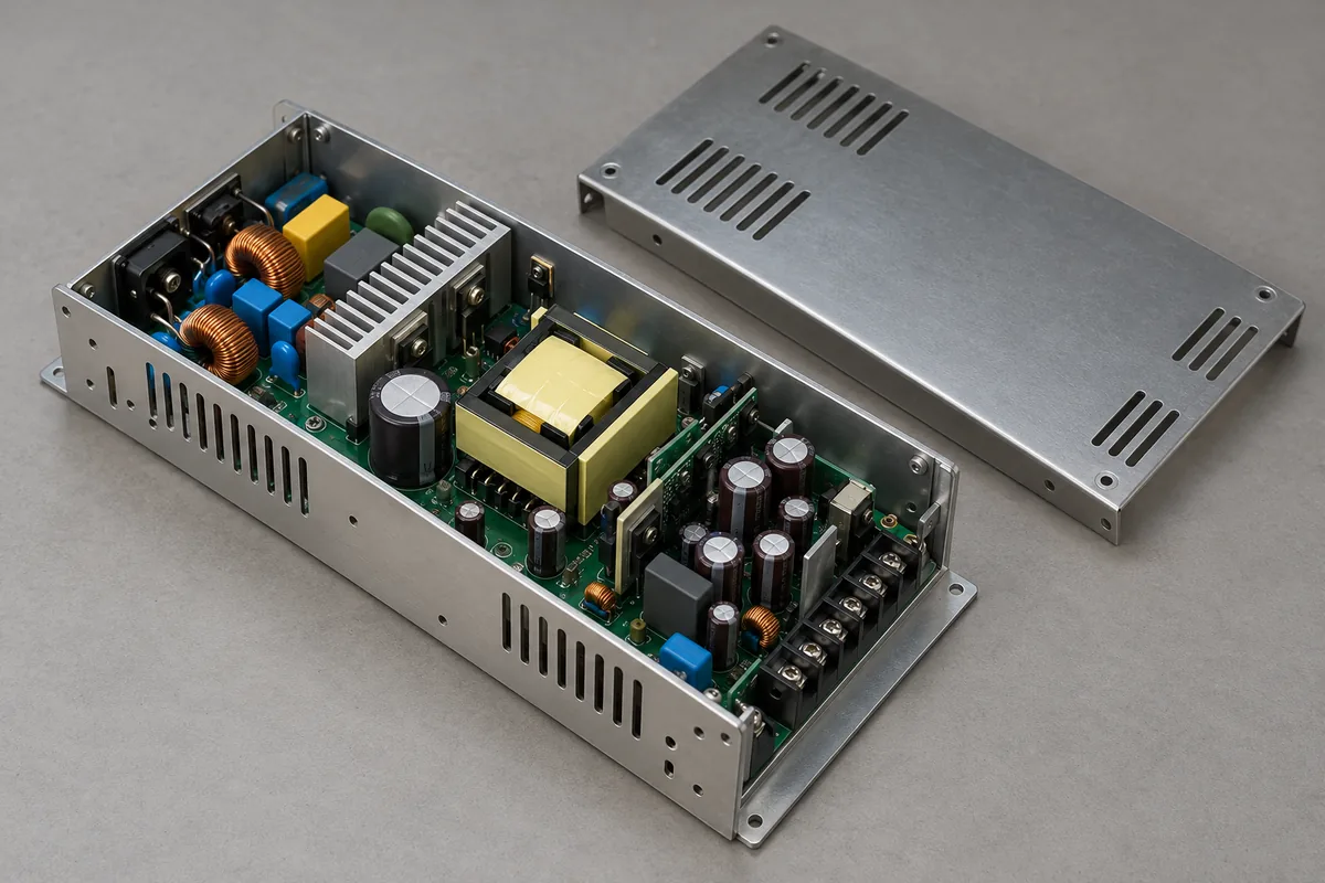
A useful historical example appears in XP Power’s manufacturer-hosted GCS component power-supply CB documentation. The retrieved file includes report 4786488107-20140916, with Amendment 1 dated April 2, 2015. It identifies GCS150PS24 among the evaluated models and describes an open-frame supply for building into Class I or Class II end products. The report is evidence of that documented assessment, not a current approval claim for an offered production unit.
Its installation conditions differ by end-product class. Class I use requires the specified protective bonding. For Class II use, the document requires separation from accessible conductive parts and reinforced insulation between primary-side mounting pads and accessible conductive chassis. The practical lesson is the relationship between board and host metal: the same component-family description does not authorize an unchanged mounting arrangement in both classes.
That example is not an industrial installation drawing. It belongs to a medical-equipment component report, and its model scope, date, and conditions must remain attached to it. Industrial equipment uses its own applicable assessment. For an actual purchase, obtain documentation covering the exact offered model, suffix, revision, and intended use instead of treating the historical example as permission to reproduce a mounting detail.
A metal housing does not settle the protection class
A metal enclosure often appears in Class I industrial equipment, but appearance cannot determine the protection scheme. Conductive parts matter because people may touch them and because mounting hardware can connect them to internal circuits. A Class II construction containing metal must preserve the required insulation relationship to accessible conductive parts. Metal itself does not rule out that construction.
Plastic provides no automatic answer either. A polymer outer box can contain exposed connector shells, panel screws, a display bezel, cable shields, or metal fittings that require assessment. It can also contain openings through which hazardous parts become accessible. Calling the housing nonconductive does not establish the insulation material properties, mechanical durability, distances, or accessibility conditions required for the completed equipment.
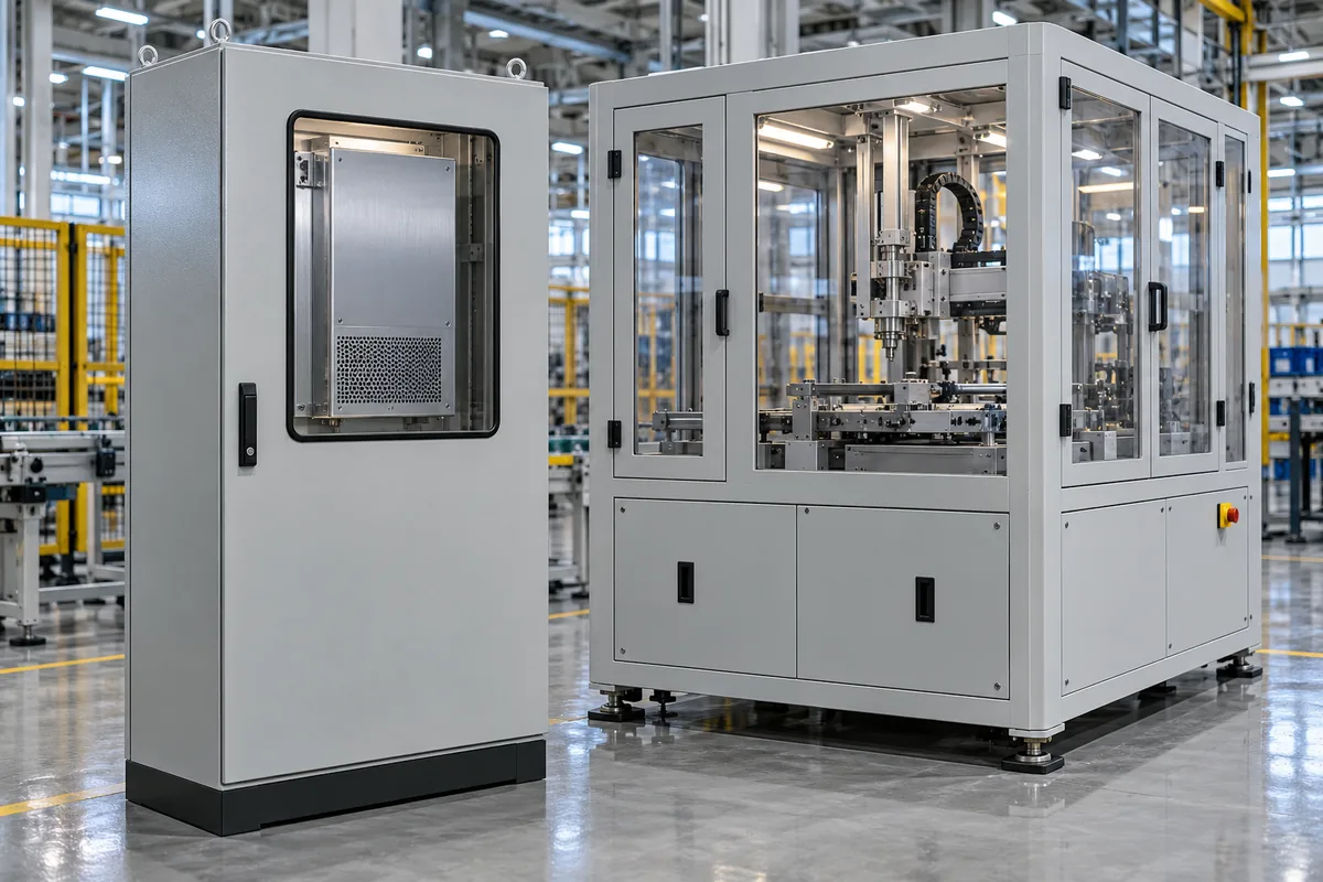
Consider a hypothetical industrial instrument with a Class II-capable open-frame converter and a metal front panel. The converter’s suitability is one input to the instrument design. The front panel, its fasteners, internal supports, wiring, and external interfaces still need the protective arrangement required by the instrument assessment. A fastener that bridges an intended insulating support can change that arrangement even though the converter part number remains unchanged.
A different instrument might place a Class II supply inside a larger Class I machine whose accessible metal requires protective bonding. The component’s insulation class does not remove the machine’s established protective-earth obligations. This is why a statement such as no earth needed must specify whether it refers to the converter, its supported mounting configuration, or the entire finished product. Those are different objects.
Protective earth, functional earth, and DC return answer different questions
Protective earth provides a safety function within the assessed protection arrangement. Functional earth serves operation, such as controlling electromagnetic interference, without substituting for protective insulation or protective bonding. DC return is a circuit conductor. A connection among these domains can be intentional in a documented design, but their names do not make them interchangeable.
Class II therefore does not mean every conductive reference in a system must float. Manufacturer guidance recognizes functional connections in some Class II applications. Whether a particular connection is permitted, required, or incompatible with the intended arrangement comes from the exact supply and host documentation. The absence of a protective-earth dependency is not general permission to disconnect a conductor that an installed machine requires.
The noise consequences also differ from the safety classification. Connecting an output reference to chassis can change the common-mode noise path. Cable shields, a connected controller, or another powered peripheral may establish a relationship that was absent during component testing. A supply’s documented emissions performance belongs to its test arrangement and cannot automatically be transferred to a different installed reference network.
For the physical distinction among earth points, filter connections, and return conductors, the separate discussion of open-frame power-supply grounding paths addresses that narrower problem. The class comparison resolves the protection concept; the mounting drawing resolves actual connection points. Neither should be used as a troubleshooting instruction to lift protective earth when interference appears.
NEC Class 2 belongs on a separate line of the specification
IEC Class II and NEC Class 2 sound alike but describe different properties. Class II concerns protection against electric shock through the insulation arrangement. NEC Class 2 concerns limited-energy circuits and their installation requirements. A Roman numeral on a supply description does not establish that its output qualifies as a Class 2 circuit.
Likewise, an output described as Class 2 does not establish the input-side protection class of the converter. Ask separately how the mains-powered equipment protects accessible parts and what evidence supports the output-circuit designation. The first answer may involve insulation and protective earthing; the second involves the applicable source limitation and circuit requirements. Do not move an approval statement from one answer to the other.
This matters in industrial panels because a substantial central DC source can feed separate limited branches. The limitation can belong to a documented downstream device rather than to the full source output. Conversely, a Class II converter may supply an output that has no demonstrated NEC Class 2 status. A low nominal voltage or modest expected load is insufficient evidence for either designation.
A specification can make the separation explicit with two independent entries: electric-shock protection arrangement for the equipment, and required designation for the outgoing circuit. Preserve the exact supporting documents for each. The two entries need not share a manufacturer or component boundary, and neither replaces conductor, connection, and installation requirements applicable elsewhere in the machine.
Keep output-energy terminology separate even within one datasheet. A general statement about isolated output, a voltage rating, or an insulation withstand test describes a particular property; it does not automatically establish a circuit designation. Ask which source and output terminals the statement covers, under which documented conditions, and whether the offered variant is included. This prevents a compliant branch accessory from being mistaken for a characteristic of every output in the cabinet.
Compare supported constructions rather than ranking the numerals
For a machine built around a documented protective conductor and bonded accessible metal, a suitable Class I supply can align with the established architecture. Its advantages are architectural continuity and a defined protective path, not a universal reliability benefit. The installation still needs the specified bonding points, mounting relationships, and protective measures for that exact converter.
A product intentionally designed without reliance on protective earth may instead need a converter suitable for Class II integration. That can remove one dependency from the shock-protection concept while increasing the importance of barriers, accessible interfaces, and mounting insulation. It does not justify operating an existing Class I machine through an unearthed adapter or deleting an established protective connection.
Supported alternatives can also have different physical and commercial consequences. An insulating support, a different inlet, additional barriers, or a revised enclosure can affect space and assembly work. Those consequences should be taken from the proposed design, rather than assumed from the class alone. There is no defensible general rule that Class II is cheaper, smaller, or more suitable for every industrial instrument.
Documentation language deserves the same care as hardware. A catalog heading may describe a family, while its installation manual distinguishes covered and open-frame versions, optional chassis, or different mounting arrangements. Preserve those qualifiers in the comparison. When the supplier states that a model supports both classes, request the conditions for each intended construction rather than recording both labels as unconditional attributes. An unanswered mounting question is a missing integration fact, not evidence that the two arrangements are equivalent.
For an existing approved machine, replacement should preserve its supported protection arrangement unless a controlled redesign establishes another one. A matching output rating does not resolve a changed earth dependency, a different mounting pad, or an accessible metal cover. For a new design, settle the equipment’s protection concept before treating candidate supplies as interchangeable. Class I versus Class II is ultimately a comparison of supported constructions: what protects the person, where that protection is provided, and which installation relationships must preserve it.