DC-side EMI filtering in server power distribution starts with a boundary question: which disturbance must be prevented from reaching which circuit? A filter at a shared bus entrance and a filter at one downstream converter do not enclose the same hardware. Reducing noise that crosses an upstream connection does not, by itself, demonstrate that neighboring loads on the downstream bus are protected from one another. Before selecting components, draw the source, distribution paths, switching loads, receiving circuit, and relevant return routes. The filter then has a defined job instead of becoming an unspecified cure for a noisy server.
This discussion concerns engineering integration of a documented server DC distribution assembly. It does not prescribe an add-on network for an unknown hot-plug PSU or authorize modifying its internal circuitry. Exact converter interfaces, permitted capacitance, grounding, protection, and operating limits remain properties of the selected hardware.
Put the source and the receiver on the same drawing
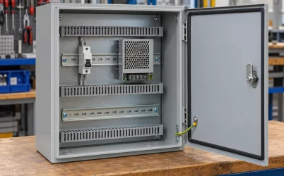
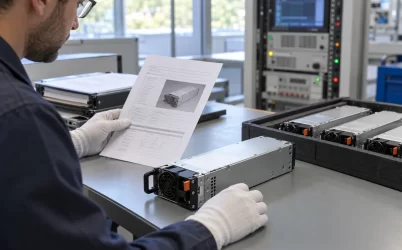
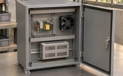
A server power path can include removable supply modules, a combining or distribution assembly, and several downstream converters. Two complete source modules beside a distribution enclosure show where the physical assemblies are located; their presence alone does not identify the electrical filtering inside them. The useful circuit drawing goes further. It names the common bus and the branches that supply the motherboard, accelerators, storage, or other supported loads, together with their intended returns.
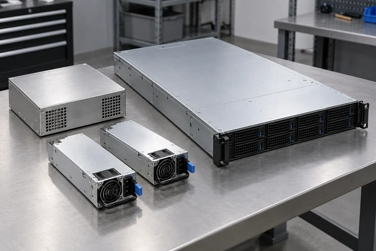
Now assign roles for one investigation. Imagine a hypothetical switching converter on branch A and an affected monitoring circuit on branch B. The converter is a suspected disturbance source, while the monitoring circuit is the receiver whose behavior matters. Neither role is permanent. A second switching stage may be the source in another frequency band or operating state. The investigation needs a particular source-to-receiver question rather than a declaration that the entire power system is noisy.
The receiving boundary also requires care. A disturbance measured at the input of branch B is different from a disturbance at its regulated output or at a signal reference used by the monitoring circuit. Local regulation, decoupling, board interconnections, and the receiver’s own response lie between those locations. A cleaner shared-bus waveform is useful evidence about that bus, but it cannot independently establish what a sensitive circuit experiences.
This distinction keeps two objectives separate. One project may need to limit conducted disturbance leaving a board through its power connector. Another may need to prevent an internal load from disrupting a neighboring function. Both can involve DC-side filtering, yet their acceptance measurements belong at different boundaries. Define the intended result before interpreting an attenuation plot.
A common entrance does not separate downstream neighbors
Consider the same hypothetical branches A and B connected to a common distribution node. Place a filter between the upstream supply and that node. Both branches now sit on the downstream side of the filter. The network may change disturbance transfer across the upstream interface, but current can still interact through the downstream paths shared by A and B. The drawing therefore contains a route between the two branches that does not have to cross the entrance filter.
This is a statement about connectivity, not a prediction of how large the disturbance will be. Actual coupling depends on the impedances and source behavior across the relevant frequency range. A sufficiently low-impedance local network may make the effect small; another configuration may expose it. The existence of a shared route identifies something to evaluate. It does not prove a fault or justify adding parts before measurement.
Moving a filter into branch A changes the boundary. The network is now between the suspected switching load and the common node. Placing it in branch B instead changes what reaches the receiving assembly. Those options need not produce equivalent results because the source and receiver have different electrical behavior, and the remaining wiring is different. A central filter, a source-branch filter, and a receiver-branch filter should therefore be compared as different circuits.
The common section matters even when the branch conductors look separate. If their return currents use a shared conductor, connector region, or board route, a voltage developed there can affect both circuits’ references. Drawing only the positive supply traces can conceal this relationship. An apparently isolated positive branch is not an isolated current loop when its return shares a consequential path.
There is no universal instruction to install a filter on every branch. Each added network consumes space and can introduce loss, stored energy, and dynamic constraints. The better question is which boundary needs an intentional impedance or return path to address a demonstrated propagation mechanism. Sometimes the relevant correction is distribution geometry or local placement rather than another centralized network.
Differential and common-mode paths ask different questions
Analog Devices’ EMI-filter design discussion distinguishes differential-mode noise associated with current in the two input conductors from common-mode paths involving parasitic capacitance and earth. Its converter example places the input filter between the local input capacitors and the source. These are bounded design concepts from a switching-converter example, not a complete server PDB prescription.
For a differential-mode investigation, identify the forward and return conductors belonging to the affected circuit. The relevant voltage is between them. A disturbance on the positive conductor relative to an unrelated chassis point does not, by itself, describe the voltage presented across the receiver’s power input. Both conductors can move relative to the chassis while their difference changes much less, or a significant difference can exist with a relatively quiet chassis observation.
For a common-mode investigation, the drawing must include the reference structure and paths outside the ordinary forward-and-return power loop. Enclosure metal, mounting interfaces, cable shields, and parasitic coupling can become relevant. These paths cannot be reconstructed from the DC wiring labels alone. They also cannot be changed casually: protective-earth and insulation arrangements impose requirements beyond the desired electromagnetic response.
Consequently, a network connected only across a branch’s positive and return conductors should not be assumed to control every disturbance involving the chassis. Conversely, changing a chassis-related path does not automatically correct differential voltage at the load. First identify what was measured and the current route consistent with it. A component called an EMI filter is not evidence that both mechanisms have been addressed in the installed assembly.
Placement determines which routes bypass the intended boundary
A board-mounted power module can have its filtering implemented partly on the host PCB. Advanced Energy’s discussion of board-module EMI emphasizes external input filtering and the importance of layout and component placement, including field coupling into nearby input conductors. That supports treating the assembled board as the engineering object rather than attributing every result to the purchased module.
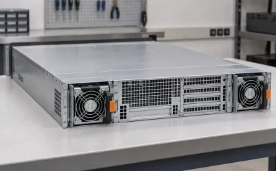
The complete server can place a downstream conversion region near its load while the source and distribution hardware occupy another area. That physical separation helps locate the interfaces to inspect. It does not reveal the converter topology, a filter value, or the path of a measured disturbance. The electrical drawing must still show where local input capacitors, branch conductors, returns, and the proposed filter connect.
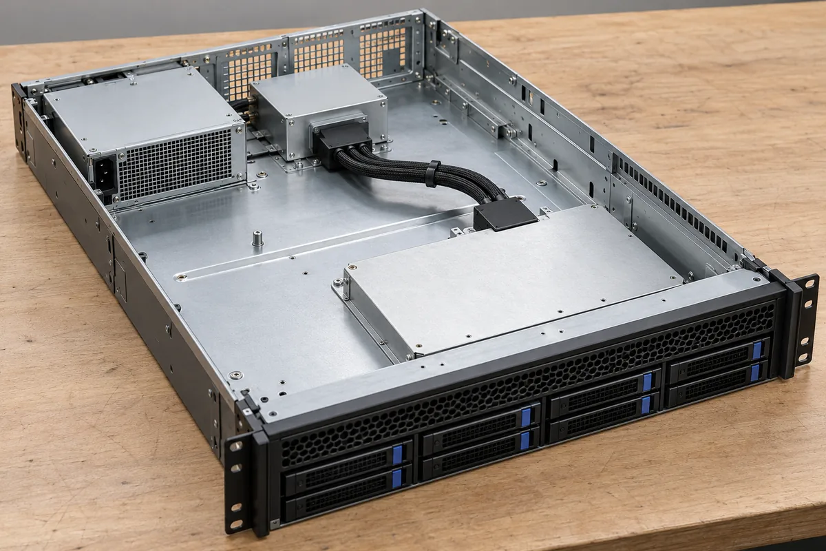
A filter boundary can be bypassed electromagnetically even when its schematic connection is correct. If wiring on opposite sides runs close together, or a switching region couples into conductors beyond the intended boundary, the physical assembly supplies an additional route. Improving the nominal network alone may then leave the receiver observation largely unchanged. This is why the layout comparison belongs beside the schematic comparison.
Keep the interpretation specific. A repeatable improvement after a documented routing change makes that route a useful participant in the explanation; it does not establish universal spacing or guarantee compliance. The same change can affect cooling, service clearance, or other interconnections. A server integration decision must retain those practical constraints while addressing the measured path.
Source population changes the connected network
A redundant server can operate with both source modules contributing, with another supported power policy, or with one source unavailable. These states change which paths carry current. They may also change the impedances presented to a downstream filter. A network evaluated with a convenient bench source is therefore not automatically characterized for every supported population of the actual server assembly.
That observation does not imply that redundancy doubles noise or that the survivor is always the worst electromagnetic condition. The answer depends on the sources, operating points, distribution hardware, and measurement. Record the documented source population and policy alongside the branch loads. Otherwise, a comparison can unintentionally combine a filter change with a different power-system state.
DC performance remains a separate acceptance requirement. Added resistance can reduce the receiving voltage under load. Capacitance changes charging and stored-energy behavior, while a filter’s impedance can interact with a regulated converter. These constraints require the selected hardware’s guidance and an appropriate engineering assessment. Lower conducted disturbance at one port is not permission to sacrifice startup, supported hot-swap behavior, or regulation.
Those checks should remain proportionate to the design question. A source-branch filtering change needs evidence about that branch and the common bus it joins. A modification near a receiving converter needs evidence about the source it sees and its documented input behavior. Neither can be accepted solely because the server boots once after the parts are installed.
Observe the crossing and the receiving function separately
Before a comparison, name the observation points, load state, source configuration, relevant frequency range, and measurement method. Preserve the assembly and routing that produced the original symptom. A different probe return or a different operating policy can change a trace without demonstrating a filtering improvement. The experiment should distinguish a changed circuit from a changed observation.
Then retain two results where the application requires both: disturbance at the chosen filtering boundary and behavior at the receiver. Suppose a hypothetical modification reduces the upstream-port observation while the monitoring error remains. That is a bounded success at the port and an unresolved receiver problem. It suggests that the original propagation model was incomplete, that another route remains, or that the symptom has a different cause. It does not justify calling the filter ineffective at the port where improvement was demonstrated.
Configuration changes deserve the same boundary discipline. Suppose the receiving board is moved to another branch connector without changing the filter. The upstream-port measurement may remain comparable, but the source-to-receiver route now includes different copper, contacts, and return geometry. A prior receiver result should not silently follow the board into that new location. Likewise, disconnecting a suspected source can remove both its disturbance and its electrical loading, so an improvement does not uniquely identify which change mattered. Controlled comparisons should record what remained connected and what operating states changed. That record lets the next engineer distinguish evidence about the disturbance generator from evidence about the network through which it travelled.
The reverse result is equally informative. A receiver can improve while a required external-port measurement remains unacceptable. The local correction has then addressed a functional path without establishing the necessary emissions result. Keep those findings separate so the next change targets the remaining objective.
A useful final drawing identifies the demonstrated source, the path the change addresses, the branch boundary it encloses, and the observations that improved. It also leaves unresolved routes visible. That is how DC-side EMI filtering becomes an accountable part of server power distribution: each network has a defined crossing to control, while the complete assembly still answers for the receiving circuit and the supported power states.