An 800W 48V industrial AC-DC power supply cannot be sized reliably by adding the motor-current readings displayed by its drives. Those readings describe a different electrical boundary. The supply feeds each drive’s DC input; the drive converts that input into controlled motor voltage and current. A large winding-current reading can therefore coexist with a substantially smaller supply-current reading. For purchasing, the useful evidence is the electrical demand at the 48 V inputs throughout the machine’s working cycle, including when axes operate together.
At exactly 48 V, 800 W corresponds arithmetically to about 16.7 A. That establishes a reference, not an operating allowance for an unspecified product. Whether a candidate can run the machine depends on its documented continuous and transient limits, the voltage reaching the drives, and the timing of their combined demand. Start by keeping the measurements separate.
Identify which current the machine is reporting
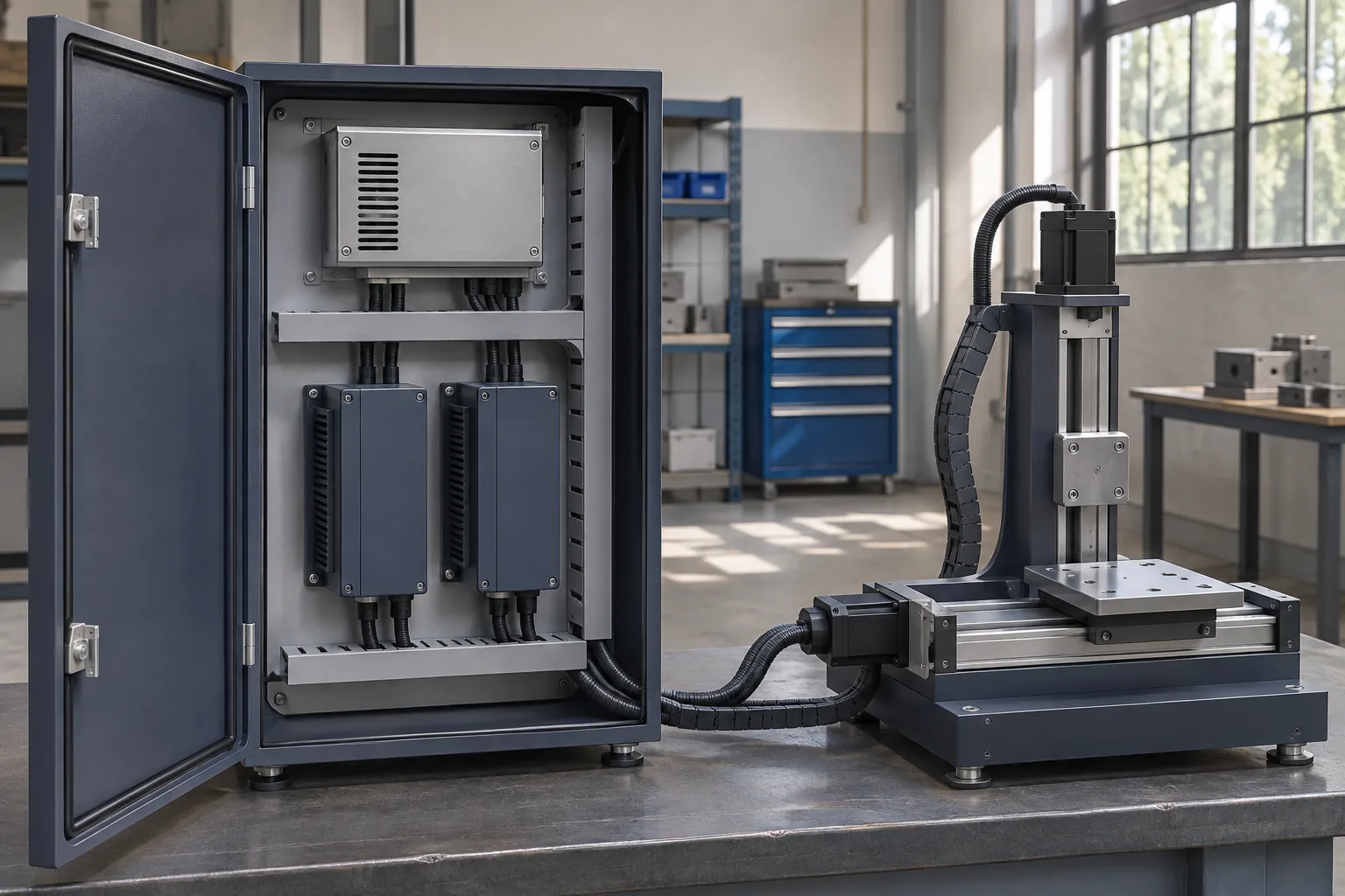
In a two-axis cabinet, the supply feeds two drive input branches, while each drive controls its own motor windings. A controller display might report torque-producing current, a phase-current quantity, or another manufacturer-defined motor-current value. A meter on the common DC feed instead observes the combined input demand of the connected drives and other loads. Both readings can be correct without agreeing numerically.
Maxon’s engineering note, Motor controllers: Input current vs. Motor current, explains this distinction through power conversion. The drive changes the voltage and current delivered to the motor; its supply current is consequently not interchangeable with its motor-current reading. This principle supports measuring the DC input directly. It does not provide a universal conversion factor for every drive, motor, or commutation method.
For a brushless motor, multiplying one phase RMS current by the full 48 V DC rail does not establish drive input power. The phase voltage is switched, phase currents have their own timing, and the displayed quantity may use a particular reporting convention. PWM duty alone is also insufficient as a general three-phase power formula. An estimate needs the drive manufacturer’s applicable method and its assumptions; a DC-port measurement avoids relying on that shortcut.
Motor mechanical output is another quantity. Shaft power describes useful mechanical transfer at the specified operating point, whereas drive input power also covers losses in the drive and motor and any equipment powered through that boundary. A motor’s mechanical rating is not a measurement of its electrical consumption during acceleration, holding, or a lightly loaded return stroke. Conversely, a high torque demand at low speed need not imply the same input power as high torque at high speed.
AC inlet current belongs upstream of the AC-DC conversion stage. It is relevant to the AC installation, but it cannot be compared directly with the 48 V branch current. Supply losses and the AC current waveform affect the relationship. Keep AC input evidence for the upstream feed and DC output evidence for the motion load; neither substitutes for the other.
Measure power at a defined DC input boundary
Place the electrical input boundary at the drive’s DC terminals. Define current into the drive as positive, measure voltage across its positive and return terminals, and record current entering that same input. The instantaneous electrical input is p(t) = v(t) × i(t). Average those simultaneous products over the interval being examined. If voltage varies, multiplying separately averaged voltage and current can give a different result.
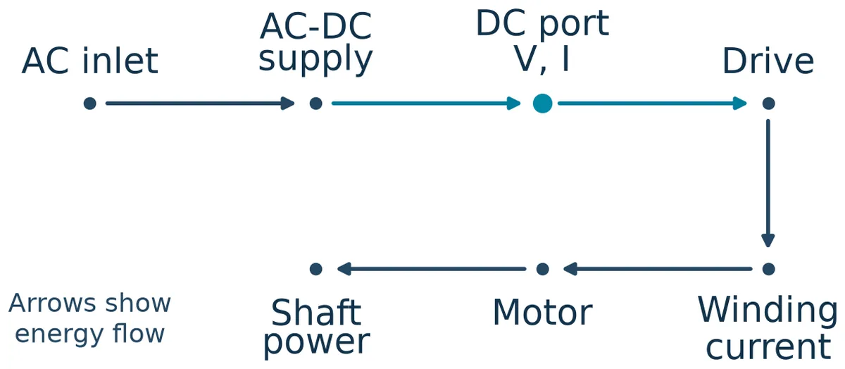
The measurement point determines what is included. A branch measurement at one drive excludes another axis. A measurement at the supply output includes all downstream branches, along with distribution losses and any charging or discharging of downstream energy storage. A drive-input measurement includes whatever electronics and peripherals that drive actually powers through its DC port. Separately powered brakes, controls, or sensors need their own contribution to the supply budget.
Local capacitors make this boundary especially important during short events. A capacitor near the drive can provide part of an input pulse while the upstream supply current changes more slowly. That does not make either observation incorrect. The two instruments are observing different locations with stored energy between them. Over a complete cycle, comparing energy becomes more informative if the capacitor begins and ends at the same voltage; otherwise, some apparent difference represents a change in stored energy.
Record the common supply output as well as the individual drive branches when possible. Branch records explain which motion created demand. The common record shows what the proposed supply must actually deliver, including auxiliary loads. Use a shared time reference or a clear synchronization event so that the axis traces can be added at matching instants. Adding unsynchronized captures can invent an overlap that never occurred or conceal one that did.
Choose instrument range, bandwidth, sampling, and averaging for the event being evaluated. A slowly updating panel meter can describe ordinary consumption while missing a short acceleration demand. A probe that clips at the event maximum understates the peak. Equally, a switching spike should not be confused with a sustained overload interval. Preserve the measurement settings and distinguish the working-cycle envelope from higher-frequency detail. Use appropriately rated instruments and approved measurement access.
Maxon’s separate publication on PWM motor-current measurement reinforces a related limit: measuring switched motor conductors requires equipment suited to the waveform, and a current-monitor label needs interpretation. A drive’s internal motor-current monitor can remain valuable for torque and winding loading. Retain it alongside the DC-input record, with its defined meaning, rather than treating it as the supply-sizing channel.
Axis overlap determines the shared demand
A supply feeding several axes sees their simultaneous input, not the sum of every axis’s maximum observed at unrelated times. The opposite shortcut is equally problematic: dividing total cycle energy by cycle time gives average power but discards when that energy was required. Both the common time trace and the cycle average have purchasing value, because they answer different questions.
Consider a hypothetical ten-second cycle with two drives and a constant auxiliary load. The following inputs are invented DC-port electrical powers, not motor ratings or test results. For this simplified example, each value is stipulated to remain constant throughout its interval, with no additional excursions. That assumption makes the interval values sufficient for the arithmetic; actual interval averages would not establish the absence of shorter peaks.
| Cycle interval | Drive A input | Drive B input | Auxiliaries | Combined input |
|---|---|---|---|---|
| 0–1 s | 520 W | 180 W | 60 W | 760 W |
| 1–3 s | 260 W | 420 W | 60 W | 740 W |
| 3–7 s | 120 W | 160 W | 60 W | 340 W |
| 7–10 s | 40 W | 60 W | 60 W | 160 W |
The combined energy is (760 × 1) + (740 × 2) + (340 × 4) + (160 × 3) = 4,080 J. Dividing by ten seconds gives a cycle average of 408 W. The greatest combined power in this constructed cycle is 760 W. Adding the separate drive maxima and auxiliaries instead gives 520 + 420 + 60 = 1,000 W, but those two drive maxima do not coincide in the stated sequence.
That distinction can reverse a purchasing judgment. The 408 W average does not establish that a source rated for 408 W can reproduce the cycle. The 1,000 W sum does not establish that the original sequence demands 1,000 W either. The relevant candidate must support the actual combined envelope, plus distribution loss and any demand outside the example, under its published operating conditions. An 800 W headline alone cannot establish that match.
Now suppose a revised machine program overlaps Drive A’s 520 W operating point with Drive B’s 420 W operating point. With the same 60 W auxiliaries, demand becomes 1,000 W during that overlap. No motor nameplate changed. The changed timing created a different source requirement. Whether a short overlap is permissible depends on the exact supply’s documented transient capability and the voltage maintained during it.
Use this reasoning for production variations as well as the nominal recipe. A heavier workpiece, shorter dwell, concurrent recovery move, or different axis order can change the shared envelope. Staggering motions may reduce concurrence, but it can also alter throughput or machine behavior. Treat the motion program as part of the electrical load description whenever the purchasing decision depends on its timing.
Lower drive voltage changes more than the current calculation
The voltage that matters to the drive is the voltage at its input terminals during motion. A supply can remain near its setpoint while a remote drive receives less because current flows through cables, contacts, and branch devices. Alternatively, several branches may dip together because the source output itself changes. Simultaneous source-terminal and drive-terminal measurements separate these situations more effectively than a single cabinet voltage reading.
For a hypothetical input demand that remains 760 W, current is approximately 15.8 A at 48 V and 17.3 A at 44 V. This calculation assumes the drive maintains that electrical input power over the stated voltage interval. It illustrates how lower voltage can increase branch current; it does not predict that every motion drive behaves as a constant-power load. A real drive may limit current, reduce performance, or stop according to its control and protection rules.
There is also a motor-side consequence. As motor speed rises, back EMF consumes part of the voltage available to establish the required winding current. Winding resistance and the voltage needed to change current also matter. The drive’s modulation and internal voltage drops limit what it can apply to the motor. A lower DC input therefore leaves less voltage headroom for some speed-and-torque operating points.
The practical symptom may appear before a clear undervoltage shutdown. A demanding acceleration or high-speed move can lose current-control margin or fail to achieve the intended motion even though the drive remains powered. The amount depends on the motor, drive, load, and trajectory. There is no general rule that a particular percentage of DC-bus sag produces the same percentage reduction in speed across all motion systems.
Evaluate the minimum recorded drive-terminal voltage against both the drive’s documented input window and the required motion performance. Raising the supply setpoint is not an automatic remedy: maximum permitted input voltage, lightly loaded conditions, and every connected device still constrain it. Reducing distribution drop and changing the source address different causes. The voltage record identifies which question the purchase must resolve.
A cycle average does not establish an overload allowance
An overload specification describes a permitted event under stated conditions. It may depend on magnitude, duration, repetition, temperature, input voltage, or recovery time. A motion-cycle average summarizes energy over a selected interval. These are different descriptions, so a low average cannot establish permission for an otherwise undocumented peak.
If the hypothetical revised cycle demands 1,000 W for 0.4 seconds, the purchasing question is whether the exact candidate supports that event at the applicable conditions and maintains usable drive voltage. A document allowing another duration or another repetition rate does not automatically cover it. Nor does a percentage describing an overcurrent protection threshold establish an operational overload rating. A protection threshold can describe where normal output ends.
The response during the event matters as much as avoiding shutdown. A supply may reduce voltage, limit current, interrupt output, or follow another documented policy. A drive can react to the resulting voltage trajectory before the supply trips. Compare the recorded demand with the published output behavior, rather than treating survival of one bench cycle as permission to exceed the documented envelope repeatedly.
Keep working-cycle demand separate from initial energization. Charging the drives’ input capacitors is a startup event; accelerating an already powered axis is an operating event. They may involve different time scales and protection interactions. A source that passes one can still fail the other. Likewise, continuous output capability remains conditional on the candidate’s specified input and installed thermal conditions, even when average motion demand appears modest.
A negative measured DC-port power needs a separate explanation. First confirm polarity and instrument convention. If energy is genuinely returning from the drive, identify a documented handling path for that operating state. A positive output-power rating does not establish that an AC-DC supply can absorb returned energy. Preserve that interval in the record instead of allowing it to cancel positive demand in an average that hides either boundary.
Put the motion record into the purchasing description
A useful request for an 800W 48V industrial AC-DC power supply describes the load at the interface the supplier must support. Provide the common output demand over time, the drive-terminal voltage requirement, the relevant motion sequence, and the conditions under which those observations apply. Include branch traces when they explain an overlap. This gives the supplier something more specific to assess than motor wattage or a screenshot of phase current.
For the hypothetical original cycle, the meaningful statement is that combined drive and auxiliary input reaches 760 W in the stipulated sequence and averages 408 W over ten seconds, before accounting for distribution losses. It is not that the machine is simply a 408 W load. If concurrent motion can instead produce 1,000 W, that alternate sequence belongs in the same description, with its duration and repetition stated.
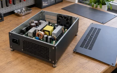
Mechanical packaging remains a separate purchasing decision. The responsibilities of open-frame and enclosed supplies affect housing, access, mounting, and installation. Those considerations determine how a suitable electrical source fits the machine; they do not convert winding current into DC input demand or establish a transient allowance.
The strongest evidence for retaining the 800 W class is a motion record that fits a candidate’s documented envelope while preserving the voltage the drives need. If the record exceeds that envelope, the useful next choice is explicit: a source with suitable documented capability, an engineered distribution change where voltage drop is responsible, or a permissible change to motion concurrence. Each follows from a different observation in the same working cycle.