An industrial control power supply should keep the controller and essential I/O within their permitted DC voltage range while the machine starts, switches loads, and handles a fault on another branch. In many control cabinets the nominal bus is 24V DC, but the correct supply cannot be chosen from that label alone. The useful design question is which loads may share the rail, which must be separated, and what happens to the PLC when a solenoid, cable, or remote device fails. Select the converter, distribution, and protection as one control-power arrangement; then verify its behavior in the finished cabinet.
This is a narrower problem than general industrial power supply selection. A machine can have a converter with ample steady-state wattage and still lose its controller when a field cable shorts or a group of coils energizes. Conversely, a controlled branch shutdown may leave the PLC running, preserve diagnostic information, and stop only the affected actuator. The distinction matters because losing a machine’s logic supply can turn a localized electrical fault into a full process interruption or an ambiguous restart.
Identify the loads that must stay powered
Begin with the machine’s control narrative, not a catalog power rating. List the PLC or controller, local and remote I/O, network devices, HMI, safety-related electronics, sensors, relay coils, valve solenoids, and any industrial computer. State what each load does during normal operation, startup, emergency stop, and loss of mains. Some devices need only ordinary control power; others must remain energized long enough to report a fault, complete a defined shutdown, or retain communication. A safety function’s supply and failure behavior must follow its approved safety design rather than a generic cabinet layout.
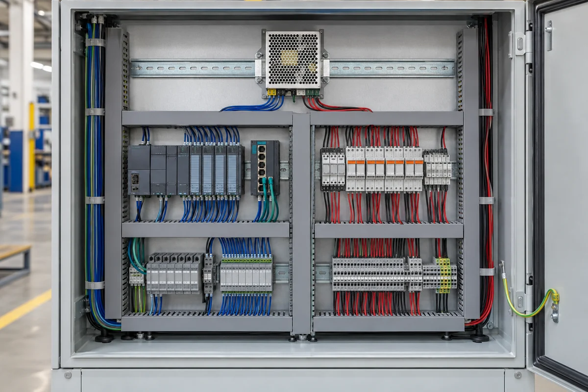
Separate the loads by consequence. A short on a field sensor cable should not automatically take down the PLC if the machine design expects diagnosis of that short. An actuator branch may be permitted to disconnect while controller, network, and alarm circuits continue. A valve coil may require a different protection response from an analog transmitter. These are functional distinctions, not just convenient terminal-block groupings. Draw the downstream branches from the DC bus and mark which ones must survive a fault elsewhere.
The power requirement is time dependent. Record the current of each device in the states that can occur together, including the charging of electronic inputs at power-up and simultaneous switching of coils. Some loads draw a brief pulse larger than their running current; others change slowly but stay elevated during operation. Use the actual device documentation and machine sequence to decide which events can overlap. Adding every peak without timing context can oversize the source, while adding only nameplate running currents can miss a startup collapse.
Where the cabinet includes an industrial PC, distinguish what must be preserved during an interruption. A PLC may recover predictably after a short dip while a PC may need time to save data or shut down. If the process needs ride-through, define its required duration and load before selecting a buffer, DC UPS, or alternate supply arrangement. Do not assume that a large power supply has enough stored energy to bridge an interruption; its hold-up behavior is model and load specific.
A shared 24V bus can turn one branch fault into a cabinet fault
A switched-mode supply reacts to overload according to its design. It may limit current, fold back, cycle in hiccup mode, or shut down and require a reset. When several DC branches share one unprotected bus, a shorted branch can pull the voltage down far enough to reset the PLC before an upstream protective device clears. The outcome depends on available fault current, branch impedance, protective-device characteristics, and the tolerance of the remaining loads. A supply labeled “short-circuit protected” primarily describes how it protects itself; it does not promise that every other control load stays online.
DC branch selectivity addresses that interaction. A suitable electronic protection module or coordinated circuit protection can disconnect the faulty feeder while leaving the source voltage available to healthy branches. Siemens describes this behavior for its 24V selectivity equipment: a shorted or overloaded feeder is isolated so other consumers, including a PLC, continue receiving power. That documented design does not mean any breaker paired with any PSU behaves the same way.
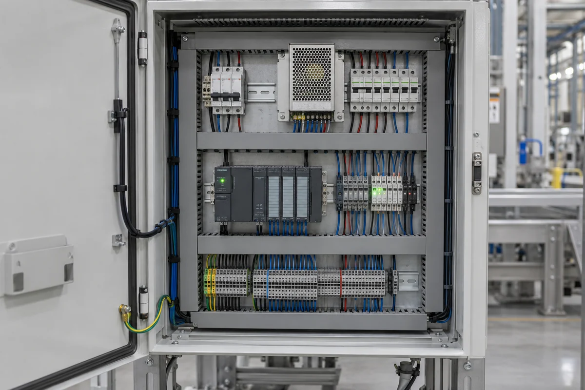
Branch protection should be chosen from the source’s actual current-limiting behavior and the impedance of the field wiring. A conventional breaker may need a fault current that a compact electronic supply does not provide for long enough, especially through a lengthy cable. An electronic branch protector may use a different trip method and report which output opened. The protection design must also coordinate conductor protection and the applicable installation rules. A quick demonstration at the PSU terminals will not necessarily predict a fault at the far end of a machine.
Distribution layout helps. Keep controller and communications loads on clearly identified branches; group actuators according to the machine’s functional zones and fault response. Avoid a single field connector that can short the entire control bus when a cable is damaged. The return path matters too: a shared, undersized return conductor can create voltage drop or noise that appears to be a supply problem. Measure at the remote load terminals and across both outgoing and return wiring during the load event that causes concern.
Power-up behavior determines whether the control sequence starts cleanly
At energization, the supply, controller, network hardware, I/O, and actuators do not necessarily become ready at the same time. A PLC might begin its boot sequence while remote devices are still charging input capacitors. Contactors may energize before a sensor network is stable. If all loads rise together and the source enters current limit, the DC bus can oscillate or climb too slowly for one device even though the eventual steady current is acceptable.
Define an intended startup order for the actual machine. It may be appropriate to establish controller and communication power first, then enable higher-current actuator branches after control logic is ready. The method could use the machine’s existing enables, dedicated distribution outputs, or separate supplies where justified. It should not bypass a required safety function. The design should say what happens after a short outage as well as after a cold start, because automatic re-energization can create a different combination of loads.
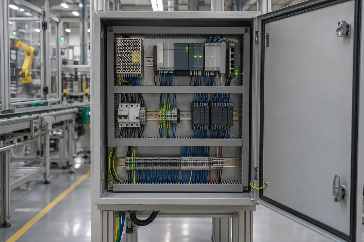
A supply’s published peak-current feature is useful only within its stated duration, repetition rate, input, and thermal conditions. It may help a short startup pulse, but it cannot be treated as continuous extra capacity for an actuator that remains energized. Similarly, a large capacitor can help a brief dip while increasing charging demand at startup. Determine whether the source and downstream protection can tolerate that charging event instead of assuming that added capacitance is always beneficial.
Observe the DC rail at the most sensitive devices during startup. A meter that averages over seconds can hide a short voltage collapse. A time-resolved measurement near the PLC or remote I/O can show whether the disturbance comes from the supply output, the branch protector, or cable drop. Record the machine state and switched loads so a repeatable event can be connected to its electrical cause.
Noise and grounding are part of control-power behavior
Industrial controls often share a cabinet with contactors, variable-speed drives, motors, and switching communications equipment. Their disturbances can reach low-voltage circuits through conduction, coupling, poor bonding, or long cable runs. The PSU’s ripple specification is one part of this picture; a quiet supply at its terminals cannot guarantee a quiet sensor rail at the end of field wiring. Keep power and sensitive signal routes organized, apply the equipment manufacturer’s grounding and shield guidance, and evaluate the completed installation.
Actuator coils can produce switching transients when de-energized. Appropriate suppression at the device may reduce the disturbance, but the suppression method can also change release time. That matters for a valve or relay whose drop-out response has a process or safety consequence. The controller, output module, coil, and suppression device should be considered together. Adding a generic diode without reviewing timing and polarity can solve one symptom while creating another.
Long field runs add DC resistance. A nominally correct 24V output at the PSU can become inadequate at a remote load when several devices draw current on the same conductors. Raising the PSU set point to compensate may overvoltage nearby loads and may not be permitted by the product’s adjustment limits. Check the permitted voltage range at both near and distant devices under maximum coincident current. Separate branches, heavier conductors, local regulation, or a different distribution layout may be more appropriate than turning the trim control.
The cabinet sets the converter’s real operating limit
Control supplies are often installed near heat-producing drives, contactors, or transformers. The relevant temperature is the air at the PSU and its cooling path, not simply the ambient outside a closed enclosure. Apply the exact model’s documented derating for temperature, mounting orientation, spacing, altitude, and airflow. If a DIN-rail unit relies on convection, tightly packed neighboring devices or blocked vents can reduce the output available in the finished panel.
Industrial control supplies may use DIN-rail, enclosed-chassis, or embedded open-frame construction. The selection follows who provides touch protection, grounding, strain relief, cooling, and service access in the finished machine. A server CRPS with a 12V output is not an automatic substitute for a 24V control bus simply because a product page calls both industrial. Powernexu’s industrial DC supply overview addresses broader input and enclosure choices; the control-specific issue here is keeping essential logic powered when another cabinet load changes or fails.
Choose monitoring that identifies the affected branch
A single “DC OK” contact tells an operator that the supply has reached a defined state, but it may not reveal which branch opened or which remote device caused a rail dip. Where the machine needs fast fault localization, use distribution equipment whose diagnostics match the required response: branch status, overload warning, event indication, or an interface to the controller. Those functions are model specific and should be included only where they improve the actual maintenance process.
Alarm timing matters. If the controller loses power at the same instant as the fault, a software alarm stored only in that controller may never be recorded. A protected logic branch, independent alarm path, or buffered controller supply can preserve the information long enough to identify the event. The value of the arrangement is operational: maintenance can distinguish a damaged field cable from a failed converter or missing AC input without replacing parts blindly.
For a control cabinet with two supplies, define what redundancy protects. Two converters connected in parallel do not automatically isolate a failed output or guarantee that one surviving unit can carry the control load. A redundancy module or another documented decoupling method may be required. If uptime needs only the PLC and network to survive, protecting that smaller critical branch can be more precise than attempting to keep every actuator powered through a source failure. The machine’s safe state still governs what may continue operating.
One useful control-power design outcome is therefore visible at the moment of a fault: the affected feeder disconnects as intended, the required controller and communications remain inside their voltage limits, the event is identifiable, and the machine enters its defined state. Those observations are more informative than the converter’s wattage alone. If they cannot be demonstrated in the actual cabinet, reconsider the branch arrangement, protection behavior, and timing before increasing the supply size.