An open frame DC-DC converter should be selected from the voltage and electrical behavior that actually reach its input terminals—not from the upstream bus label alone. Define the source during startup, normal operation, disturbances, shutdown, and recovery. Then match an exact converter model to the load voltage, current, transients, isolation boundary, cooling arrangement, mounting geometry, protection behavior, and enclosure. A nominal 24 V or 48 V source is only the beginning: batteries, long cables, chargers, switched feeders, and input filters can create operating conditions that a category-page voltage label does not reveal.
Quick answer: begin at the converter input terminals
Build the shortlist around two state maps. The input map describes minimum and maximum terminal voltage, ramp behavior, dips, surges, interruptions, source impedance, and recovery. The output map describes startup current, continuous load, transient demand, permitted voltage deviation, shutdown behavior, and fault response. After that, decide whether galvanic isolation is required and assign cooling, mounting, touch protection, fusing, EMC, and final-equipment compliance to the converter or host. Compare only exact models whose documentation addresses those conditions.
Two category words still leave the product undefined
DC-DC converter identifies the broad conversion role: a DC input is converted into one or more DC outputs. It does not establish whether the product is isolated, regulated across the entire advertised input range, suitable for a battery bus, protected against reverse polarity, or capable of tolerating a particular transient.
Open frame normally indicates exposed converter electronics rather than a fully enclosed supply. It does not identify one mounting standard. Search results may include a PCB on standoffs, a baseplate-mounted assembly, a partially covered chassis module, or a board intended to become part of a larger enclosure. Some listings include terminal blocks or wire harnesses; others expose pins, pads, or headers whose mating hardware remains outside the quoted product.
This is also distinct from an AC-input product. If the available source is utility or generator AC, the appropriate first conversion stage belongs in the industrial AC-DC power supply module category. Adding an external rectifier to a DC-DC candidate changes input protection, filtering, hold-up, safety, and compliance responsibilities; it is not merely a connector adaptation.
| Search-result description | What it may identify | What remains unresolved |
|---|---|---|
| Open-frame board | An exposed converter assembly with mounting holes and onboard components | Required enclosure, airflow, terminals, clearances, and protective components |
| PCB-mounted module | A converter intended to be soldered or socketed onto a host board | Host PCB layout, heat removal, pin functions, and assembly process |
| Baseplate or chassis module | A mechanically supported converter using a plate or partial cover | Whether the baseplate is a required thermal interface and how it must be mounted |
| Converter family page | A group of products sharing a commercial or technical family name | The exact voltage variant, rating conditions, dimensions, interfaces, and order code |
Normalize these package boundaries before comparing price or power. A lower-cost exposed board and a baseplate module may perform similar conversion, yet transfer very different thermal and mechanical work to the integrator.
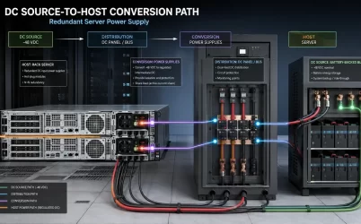
Specify the DC source at the converter terminals after wiring, protection, switching, and filtering. A nominal bus label does not capture cable drop, battery charge voltage, ramp behavior, or switching events.
| State | Record at the converter |
|---|---|
| Startup | Start voltage, ramp, inrush, and enable timing |
| Normal | Minimum and maximum voltage, ripple, source impedance, and current |
| Disturbance | Dip, surge, and interruption amplitude and duration |
| Shutdown | Decay, backfeed, reverse energy, and discharge |
| Recovery | Restart threshold, delay, and latch or reset behavior |
At low line, estimate current with model-specific efficiency, then size conductors and protection for that condition. Treat continuous range, transient withstand, undervoltage, and restart as separate specifications. Follow manufacturer input-network guidance and validate the complete source-filter-converter combination.
Write the output requirement as behavior at the load
A catalog filter usually begins with output voltage and rated power. The load, however, experiences voltage after the converter output terminals, connectors, traces, and cables. The requirement should state the permitted voltage at the load during each meaningful operating state and allocate the allowable drop between the converter and distribution path.
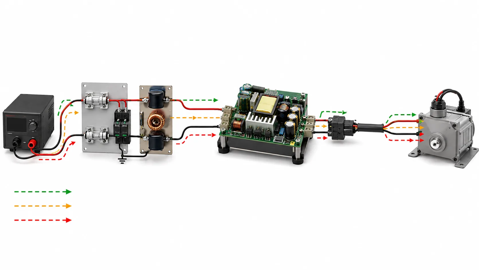
For a static load, voltage, continuous current, tolerance, ripple, and expected ambient conditions may define much of the requirement. Dynamic industrial loads need additional coordinates:
- startup or charging current and how long it persists;
- the size, slew rate, duration, and repetition of load steps;
- the permitted voltage excursion and recovery behavior;
- operation at no load or light load, if that state occurs;
- the required shutdown sequence and output discharge time;
- possible reverse energy from motors, actuators, capacitive rails, or another powered source;
- the acceptable response to overload, short circuit, and overvoltage.
Protection names are not complete behavioral specifications. Overcurrent protection may limit current, enter a cyclic restart mode, shut down until input power is recycled, or behave differently with different fault impedances. A load that must recover automatically after a temporary short needs different behavior from equipment that requires a latched shutdown. The exact model documentation must establish which response applies and under what conditions.
Control features deserve the same treatment. Remote on/off, power-good, sense, synchronization, or trim functions may use model-specific voltage domains, polarities, timing, and reference points. Their presence in a family description does not prove that every variant implements them identically. If the application requires intentional output adjustment rather than a fixed setpoint, the control window and its current, power, startup, and protection consequences need a separate adjustable-supply analysis.
Place the isolation boundary before comparing efficiency or cost
An isolated converter provides a galvanic separation boundary between its input and output circuits. A non-isolated converter normally shares an electrical reference across the conversion stage. Neither architecture is universally preferable: the choice follows the machine’s grounding, safety, noise, fault-containment, and signal-interface requirements.
Begin with a drawing that shows the upstream DC source, chassis or protective earth, converter input return, converter output return, load ground, communication interfaces, and any other conductive paths. Isolation inside the power converter does not isolate the system if a signal cable, shield, mounting feature, or second power source reconnects both sides elsewhere.
Where isolation is required, the term alone is insufficient. The exact documentation should identify the applicable isolation test, intended working conditions, insulation construction or safety classification where relevant, and any layout or mounting conditions needed to preserve spacing. A dielectric test voltage is not automatically the permitted continuous working voltage, nor does it independently establish that the converter forms the required safety barrier in the finished equipment.
Isolation also affects conducted noise and fault behavior. Coupling components, shields, chassis connections, and output grounding can influence common-mode current. The host’s EMC strategy should therefore be developed with the converter’s recommended filtering and grounding arrangements. A floating output may be intentional, but it should not be created accidentally by omitting the system grounding decision.
The host owns what the exposed board leaves unfinished
An open converter board makes efficient use of the host enclosure, but the enclosure becomes part of the power system. The broader industrial power architecture should assign these responsibilities before a board is approved.
Mechanical integration
Compare the maximum board outline, component height, mounting-hole coordinates, connector locations, and keep-out zones with the real enclosure. Include access for tools, terminal mating, cable bend radius, strain relief, and removal. Standoffs and fasteners must support the board without unacceptable flex or contact with conductive surfaces. Required electrical clearance must be maintained around the board, not only between components drawn on it.
Cooling in the installed orientation
Open-frame power ratings are conditional on the documented temperature and cooling arrangement. Determine where ambient or inlet temperature is measured, whether natural convection or forced airflow is assumed, the airflow direction, and whether a derating curve applies. A fan’s nominal airflow does not prove that air reaches the converter after filters, ducts, wiring, and adjacent boards add resistance. Component hotspots can also move when the board orientation or nearby heat sources change.
Input and output protection
Do not assume the exposed board includes every system protection element. The host may need branch fusing, reverse-polarity protection, surge suppression, inrush management, disconnects, output distribution protection, or energy-limiting measures. Place each protective device according to the fault it is intended to contain. A fuse located far upstream may protect a feeder while leaving a thin internal conductor or board trace inadequately coordinated.
Enclosure and final-equipment obligations
The host commonly supplies protection against accidental contact, conductive debris, contamination, mechanical impact, and cable pull. It also determines bonding, ventilation openings, service access, and separation from other circuits. Product-level approvals or test reports can support a final design, but they do not automatically transfer to a different enclosure, wiring arrangement, environment, or end use. System-level safety and EMC responsibilities remain attached to the finished equipment and its applicable requirements.
Compare exact models rather than category tiles
Manufacturer category pages are useful for discovering product families. For example, the MEAN WELL DC-DC converter solutions page identifies documented product routes, but an exact model’s datasheet, installation information, drawings, and ordering structure must support the actual selection. A family image or distributor filter cannot establish variant-specific input range, power, isolation, mounting, or thermal conditions.
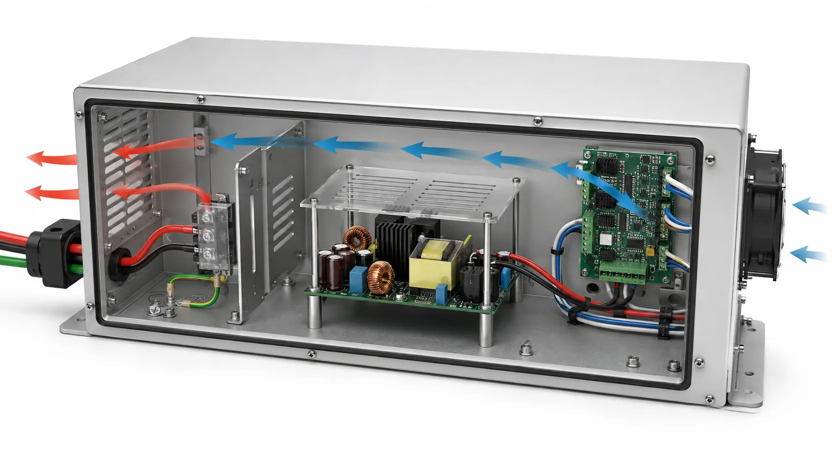
Use one row per exact orderable model. Do not combine the most favorable properties of several family members into a composite candidate.
| Comparison field | What to record | Evidence needed |
|---|---|---|
| Product identity | Manufacturer, exact model, output variant, revision where applicable, and package type | Manufacturer model page, datasheet, and quotation describing the same item |
| Input bus fit | Continuous terminal range, startup behavior, current, undervoltage response, and documented disturbance tolerance | Exact-model electrical data and application guidance |
| Output behavior | Voltage, current, power, regulation, ripple, transient response, startup, shutdown, and fault response | Specified conditions and curves applicable to the selected variant |
| Isolation boundary | Isolated or non-isolated architecture, relevant ratings, grounding assumptions, and unresolved external paths | Exact-model safety and electrical documentation |
| Thermal conditions | Temperature reference, cooling method, orientation, derating, and any baseplate or heatsink dependency | Thermal curves, installation instructions, or manufacturer guidance |
| Mechanical fit | Board envelope, component height, hole pattern, keep-outs, terminals, and service clearances | Dimensioned drawing for the exact hardware revision |
| External responsibilities | Fuse, filter, surge suppression, reverse-polarity protection, enclosure, bonding, and airflow | Installation documentation plus the host design record |
| Commercial scope | Included terminals, covers, heatsinks, cables, mounting parts, documentation, and permitted substitutions | Supplier quotation tied to the exact manufacturer identity |
A blank field is not evidence of acceptable behavior. It is an unresolved condition whose consequence depends on the intended use. Missing terminal torque information may delay assembly planning; missing isolation evidence may disqualify a candidate from an application where the converter is expected to provide a safety boundary. Give each omission a technical consequence instead of treating every gap as equal.
Price and availability become comparable only after the candidates refer to equivalent supplied objects. A bare board, a board with an optional cover, and a baseplate assembly may carry different integration costs even when their headline voltage and power are similar. Include the host-side fuse, filter, heatsink, fan capacity, connectors, mounting hardware, enclosure space, and engineering work when comparing architectures.
The bus definition removes false candidates early
A useful product search can be narrowed in a deliberate order. First remove candidates whose continuous input envelope cannot cover the terminal voltage range. Next remove products whose startup, disturbance, or recovery behavior conflicts with the source. Then apply output-state, isolation, thermal, and mechanical constraints. Only the surviving exact models should enter detailed price and availability comparison.
The resulting specification can be concise: it names the upstream source and its five states, the required output behavior at the load, the intended isolation and grounding boundary, the installed cooling and mounting conditions, the protections supplied by the host, and the exact documentation expected for the quoted model. That record does not claim universal interchangeability. It turns “open frame DC-DC converter” from a broad marketplace category into a board that has a defined electrical role inside a specific machine.