A DC redundant server power supply is a redundant DC-input conversion assembly that accepts a defined upstream DC source and delivers power through a documented module, distribution, and host interface. It is not simply a server PSU with a DC output, and it is not automatically identified by a listing that contains “DC,” “redundant,” and a wattage. For a purchase-ready result, trace the path from the facility or battery-backed DC source to the server load, then document which assembly performs conversion, isolation, combining, standby power, control, and distribution.
Quick answer: Screen candidates in this order: prove that DC describes the input; record the source voltage, current, polarity, grounding, protection, transient, and startup conditions; identify whether the offer contains modules or the complete cage, PDB, harness, and controls; calculate the required surviving capacity; and match the exact host interfaces and cooling direction. A candidate that merely produces DC, or an AC-input CRPS module marketed as redundant, should remain outside the DC-input shortlist until its conversion boundary is documented.
First decide where “DC” enters the power path
Commercial search results compress several different products into similar language. A server PSU may accept AC from a rack PDU and produce a low-voltage DC bus. A DC/DC server supply may accept an external DC bus and regulate it for the server. A listing may also use “12V DC” or another DC value to describe only the output rail inside the host. Those are different conversion roles, with different upstream responsibilities and different compatibility questions.
The defining question is not “Does the product mention DC?” It is: what electrical energy reaches the PSU input terminals, and what conversion takes place inside the quoted assembly? A true DC-input redundant supply should have documentation identifying a DC input interface and its applicable operating envelope. The documentation should not rely only on a photograph, a marketplace title, or a downstream output voltage.
PowerStream provides a commercial example of a category described as DC/DC, DC-input mini-redundant industrial ATX supplies. That page supports the existence of this product category, but it does not qualify every model for every server or prove the required input range, host interface, hot-swap behavior, or degraded-load capability. Candidate-level claims still require the exact model’s technical documentation and the target host’s interface records.
| Search-result wording | Possible meaning | Evidence needed before classification |
|---|---|---|
| DC redundant server PSU | DC-input redundant converter, but the product boundary is unclear | Input specification, module architecture, assembly drawing, and supplied-hardware list |
| 12V DC server power supply | 12V input, 12V output, or an incomplete description | Named measurement point, input/output designation, polarity, and conversion diagram |
| Redundant CRPS | Usually a modular front-end family, potentially AC-input depending on the exact product | Exact model documentation and confirmation of the source type |
| DC output redundant PSU | Possibly an AC-input supply whose output is redundant | Input-side nameplate and source-to-load architecture |
This first screen prevents an expensive category error: comparing a DC-input converter with an AC-DC front end simply because both have removable modules or a similar wattage label.
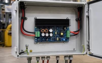
Map the assembly as one chain: upstream DC source, branch protection and disconnect, conductors, module inputs, conversion modules, combining or isolation stage, PDB, harnesses, and server loads. Assign an owner and evidence source to every boundary. The source owner defines voltage variation, fault current, grounding, and transfer behavior; the PSU manufacturer defines the accepted input envelope, conversion, protection, cooling, and management behavior; and the host or PDB owner defines combining and downstream distribution.
Mark the first common point between redundant paths. Separate feeders may still share a fuse, busbar, connector, PDB trace, standby converter, or control supply. Also record whether polarity protection, reverse-current isolation, standby conversion, and ORing reside in the module, PDB, or upstream installation. The drawing should state the exact failure boundary being purchased rather than imply protection against every source or distribution fault.
Specify startup, degraded, and recovery states before wattage
Module wattage becomes meaningful only after the operating states are defined. A DC source can behave differently during normal operation, rectifier transfer, battery discharge, cold startup, source recovery, and branch reconnection. The server can also present different demand during processor initialization, accelerator enumeration, storage spin-up, fan ramp, or a controlled workload transition.
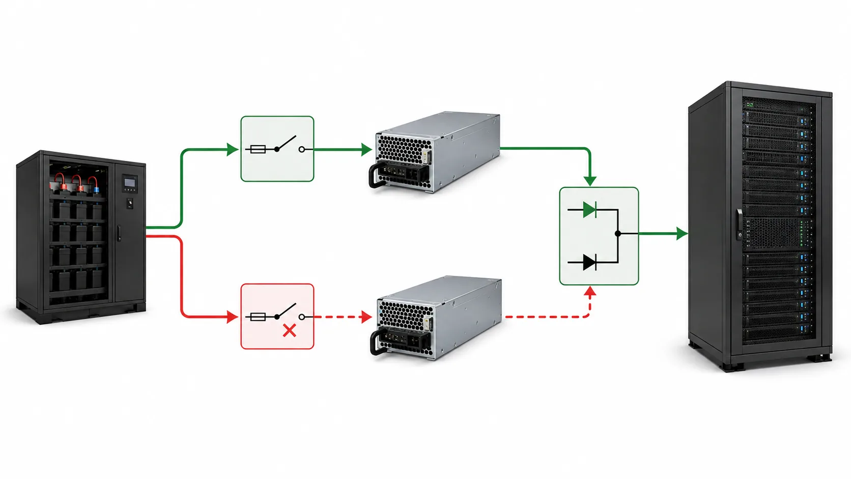
At minimum, separate these states:
- Normal operation: the expected source condition, module population, host workload, inlet temperature, airflow, and management policy.
- Degraded operation: the specified module or source branch is unavailable while the required server load continues.
- Startup: input inrush, output sequencing, standby activation, host turn-on, and any simultaneous load demand.
- Service: removal and insertion of a module or source path, including the available capacity during the intervention.
- Recovery: restoration of the source or module, current rebalancing, alarm clearing, and return to the intended redundant state.
For a 1+1 arrangement, the relevant protected output is commonly the documented usable output of one surviving module under the applicable source and thermal conditions, not the sum of two nameplates. That principle changes if the host’s operating policy permits both modules to carry a load that cannot be supported by one, in which case the system may have capacity sharing without full single-module continuity for that load. The quotation should state which condition applies.
A simple source-current calculation can expose an upstream design problem. Suppose a hypothetical server load requires 1,200 W of regulated DC output and the conversion efficiency at the relevant operating point is assumed to be 90 percent. The source must provide approximately 1,333 W before accounting for auxiliary consumption. At a nominal 48 V source, that is about 27.8 A; at a nominal 12 V source, it is about 111 A. These are illustrative inputs, not product ratings. The result shows why source voltage, branch protection, connector temperature rise, and conductor layout belong in the DC-input specification even when the server’s downstream load is unchanged.
Redundancy exists only when the surviving source branch, converter, isolation stage, PDB path, cooling condition, and control state can support the required load. Two modules may protect against one converter failure without protecting against a shared rectifier, battery string, fuse, busbar, standby converter, or management fault. Name each covered event and the first shared component.
Current sharing must be documented for the exact module-to-PDB assembly; identical housings and wattage do not prove stable sharing or fault transfer. Hot-swap capability is also conditional on connector sequencing, precharge or inrush control, isolation, capacity margin, host behavior, and an approved service procedure. Powernexu’s 1+1 CRPS power distribution board reference explains the combining, isolation, standby, management, and distribution roles, but it does not establish compatibility for an unrelated DC-input module.
Create one interface schedule from the DC source to every host load. Record input termination, polarity, keying, conductor arrangement, current limit, protective contacts, module-to-PDB connection, mating revision, and downstream destinations. Add separate rows for enable, presence, power-good, faults, sharing, fan control, temperature reporting, and management buses. A communication interface does not by itself prove BMC recognition or policy support.
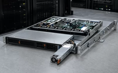
Pin assignments must remain tied to the exact module, PDB, host, revision, and connector-view convention. Powernexu’s server PSU connector interface map provides a method for naming these boundaries without implying a universal pinout. Keep mechanical and thermal conditions in the same schedule: module envelope, insertion path, latch clearance, connector datum, airflow direction, fan ownership, inlet temperature, harness bend radius, and obstructions. Physical insertion alone does not prove electrical or thermal compatibility.
Turn unresolved fields into an orderable RFQ
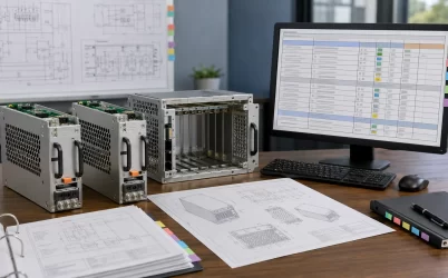
A product-heavy SERP is useful for discovering candidate families, but a supplier quote must convert the search phrase into a controlled deliverable. Ask the supplier to identify the exact manufacturer, model, revision, module quantity, input type, and assembly scope. The scope should explicitly say whether the offer contains bare modules, a matched redundant set, a cage, PDB, input harness, output harnesses, mounting hardware, fans, cords, and management accessories.
| RFQ field | Required question | Acceptable evidence |
|---|---|---|
| Conversion role | Does the quoted assembly accept DC at its input and what output domain does it create? | Model datasheet, block diagram, or manufacturer technical drawing |
| Source envelope | What nominal, minimum, maximum, transient, polarity, and grounding conditions apply? | Exact-model electrical specification and installation requirements |
| Protected capacity | What load remains supported after the named module or source path is lost? | Rating conditions, derating data, redundancy instructions, and host load definition |
| Assembly boundary | Which modules, PDB, cage, harnesses, controls, and mounting parts are included? | Bill of materials, assembly drawing, and quotation exclusions |
| Host interface | Which server, PDB, firmware, connectors, signals, and load branches are supported? | Platform compatibility record, interface control document, or approved configuration list |
| Service and management | Is live replacement supported, and how are faults, presence, sharing, and telemetry reported? | Service procedure, management specification, and operating-state documentation |
Require the supplier to identify unresolved fields instead of filling them with “standard,” “universal,” or “compatible.” A quote that permits an unspecified equivalent should not silently inherit the evidence of the reviewed model. If an exact DC-input assembly cannot be documented, the procurement path may need to move to a custom server power supply request rather than treating an AC-front-end or output-only product as an equivalent.
Use evidence to separate candidates before purchase
After the RFQ responses arrive, classify each candidate into one of four practical groups: a documented DC-input redundant assembly; a DC-input module requiring a separately specified PDB or host; an AC-input redundant supply that does not meet the source boundary; or an unresolved listing that requires clarification. This classification is more useful than a long list of wattages because it removes products that cannot perform the required conversion role.
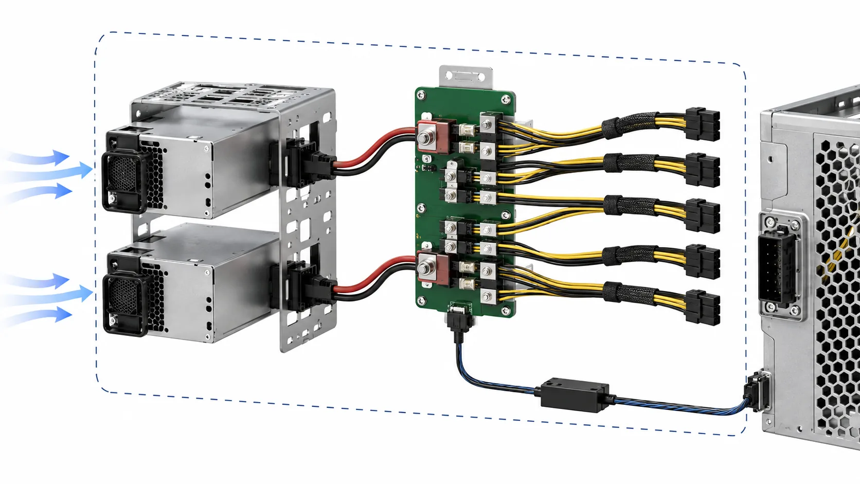
Then reconcile the model identity across the datasheet, assembly drawing, interface information, quotation, and host documentation. Each source should support only the claim it can actually prove. A datasheet may establish input and output limits for a module. A PDB drawing may establish mating geometry and downstream connections. A server platform record may establish supported population and management behavior. None of these documents alone necessarily proves the complete source-to-host assembly.
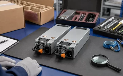
Receiving inspection should preserve this identity. Check the delivered model and revision, module quantity, labels, keying, cage and PDB hardware, harnesses, airflow markings, and documentation against the quotation. Do not energize an unknown assembly merely because its connector appears correct. For a new integration, the first powered checks should be performed under the supplier’s and host’s procedures, with polarity, source protection, standby behavior, output state, alarms, and load limits defined in advance.
Live module removal or source-loss testing is appropriate only when the platform documentation, site safety rules, available capacity, and continuity plan permit it. The intended result is not simply that the server remains on. It is that the specified failure produces the documented output, alarm, telemetry, thermal, and recovery behavior, and that the system returns to its protected state after restoration.
Keep the conversion path attached to the part number
The useful deliverable from a DC redundant server power supply search is a source-to-host identity: one exact module or assembly, one defined DC input envelope, one conversion boundary, one protected operating state, one interface and cooling arrangement, and one unambiguous bill of supplied hardware. This record allows a genuine DC-input candidate to be compared with another genuine DC-input candidate without mixing modules, complete systems, AC front ends, and output-rail descriptions.
If any boundary remains unresolved—especially the source type, input protection responsibility, surviving capacity, mating PDB, control behavior, or assembly contents—the candidate is not yet equivalent to a qualified system. Holding that distinction in the RFQ and service record is what prevents a plausible catalog match from becoming an unusable spare or an incomplete server power integration.