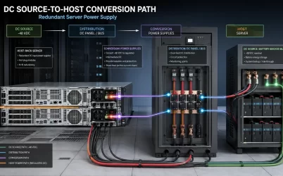
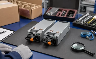
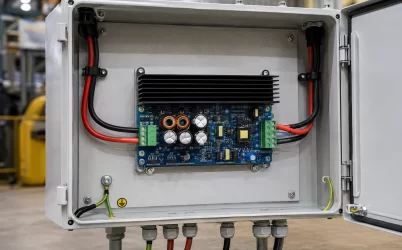
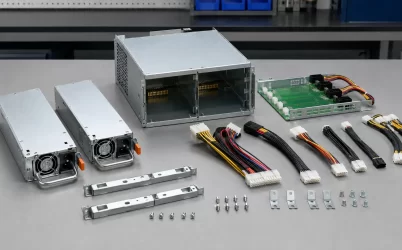
A mini redundant server power supply should be shortlisted by the space required to install, connect, cool, and service the complete assembly—not by the dimensions of one removable module. The word “mini” has no single purchasing definition. A listing may describe one converter, a two-module pair, a cage with a power distribution board (PDB), or a platform-specific kit. Before comparing price or wattage, name the exact supplied object and target chassis. Then reserve its installed envelope, connector and cable space, ventilation clearance, insertion path, extraction path, and technician access. A compact candidate that fits while stationary but cannot be removed without disturbing storage, fans, cards, or wiring is not a serviceable fit.
“Mini” does not identify the object occupying the chassis
Product-heavy search results often place physically different items under the same compact or mini description. Dimensions and prices become misleading when one seller measures a single hot-plug module while another describes the complete redundant assembly. The comparison unit must therefore be established before any dimensional ranking begins.
| Listing object | What may be included | Space-budget consequence |
|---|---|---|
| Single removable module | One converter module, sometimes without the mating cage or PDB | Module dimensions do not show the complete installed footprint or downstream connection space. |
| Redundant module pair | Two matching or associated modules | The pair still may require a separately sourced cage, PDB, retention hardware, and harnesses. |
| Complete redundant assembly | Modules, cage, combining or distribution hardware, and possibly output cables | The assembly is the appropriate object for chassis-space planning, subject to confirmed contents. |
| OEM-supported spare or kit | A module or kit associated with named server platforms | Platform support can be more important than generic compactness, but the exact kit contents still need to be identified. |
An exact manufacturer product record, such as Athena Power’s page for a named redundant-power model, is useful because its claims are attached to one identifiable product. It should not be treated as a definition for all mini redundant supplies. The same discipline applies to every candidate: use the source to establish the model and documented configuration, then keep unresolved chassis or interface questions open.
A practical candidate description might read: “two removable AC-DC modules installed in one supplied cage with a named PDB and specified output harnesses.” If the quotation can state only “mini redundant PSU,” it has not yet identified the physical object whose space is being compared.
The compactness budget includes occupied and reserved space
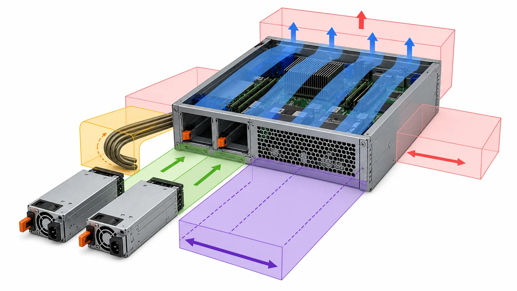
A useful space budget extends beyond the sheet-metal body. It accounts for space occupied permanently and space that must remain available during connection, cooling, and service. At minimum, record these zones for each exact model or assembly:
- Installed body envelope: the complete cage, mounting flanges, latches, handles, fasteners, rails, and other protrusions in the installed state.
- Mating-hardware envelope: the PDB, backplane, blind-mate connector, adapter, brackets, and any structural support behind or beside the modules.
- Connection envelope: plug bodies, strain relief, cable bend space, harness branching, and room to release connector locks without pulling on conductors.
- Ventilation keep-outs: unobstructed regions around documented inlets and outlets, including the effect of neighboring walls, boards, cable bundles, and fan structures.
- Insertion corridor: the unobstructed path from the service opening to the seated position, including alignment with guides and the connector.
- Extraction corridor: the path required to unlatch, pull, support, and completely remove either module.
- Working access: room for a technician’s hand, approved tool, latch movement, cable release, inspection, and safe handling of the removed module.
These regions should not be reduced to one bounding-box volume. A long, narrow module can have a smaller calculated volume yet consume more usable chassis depth or interfere with a motherboard zone. A short assembly can require additional rear connector space. A compact cage can also lose its advantage if its cables must cross fan intakes or occupy the only path available for storage servicing.
Once a candidate reaches this stage, model-specific dimensions can be transferred into a mechanical fit drawing with coordinated datums and movement envelopes. That detailed drawing answers whether the exact hardware can occupy the proposed bay. The compactness budget serves a different purpose: it prevents candidates with impractical connection or service demands from reaching that effort-intensive stage.
The extraction path often determines whether “mini” is useful
Redundant supplies are frequently purchased to permit continued operation after one supported power path becomes unavailable. That operational objective is weakened if replacing a module requires moving unrelated server hardware. The service path should therefore be evaluated for each module independently, not only for the assembly as a whole.
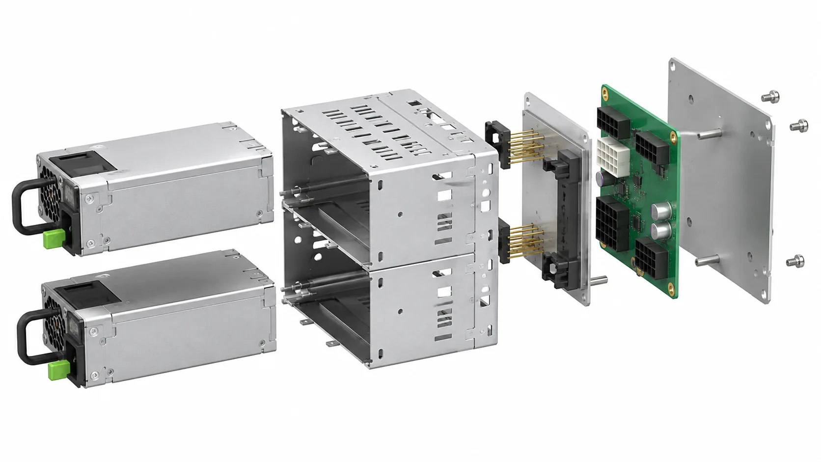
Begin at the fully seated position and trace the physical removal sequence in reverse. Can the handle or latch complete its motion? Can the module move far enough to disengage its mating interface before it contacts a rear rail, cable-management arm, rack post, or chassis cover? Once disengaged, is there enough room to support and remove its full length without tilting it through another component’s space?
Inside a compact chassis, likely conflicts include fan housings, storage cages, risers, full-height cards, motherboard heat sinks, rear I/O structures, and cable bundles. External conflicts can include rack doors, PDUs, cable-management hardware, unusually deep plugs, or insufficient clearance behind the server. The power assembly may pass a stationary fit test while failing this movement test.
Service direction also changes the value of a compact layout. Rear-removable modules can preserve internal access but require suitable rack-side clearance. Internally removable modules may reduce rear protrusion but can require opening the server and disturbing airflow baffles or adjacent hardware. Neither arrangement is universally preferable; the useful design is the one that matches the site’s authorized service method and available access.
Hot-swap wording does not remove these mechanical constraints. It describes a supported electrical and platform behavior only when documented for the exact configuration. It does not prove that a technician can physically reach and exchange the module in the proposed chassis or rack.
Cooling clearance can consume the saved chassis volume
Compact packaging concentrates conversion hardware into less space. For a given output and efficiency, reducing the enclosure can increase thermal density and make the documented airflow path more sensitive to blockage. The evaluation should follow the exact model’s airflow direction and operating conditions rather than assuming that any opening can serve as either inlet or exhaust.
Map the PSU openings against the host’s pressure zones and nearby obstructions. A cable bundle placed against an inlet, a PDB installed too close to an exhaust, or a solid chassis partition beside a perforated panel can change the air available to the module. Empty-looking space is not automatically usable if it belongs to the cooling path.
The degraded operating state deserves particular attention. In a supported redundant arrangement, loss or removal of one module can transfer more of the electrical load to the remaining converter. Depending on the platform and PSU design, that state may change conversion loss, fan behavior, or airflow requirements. The chassis layout must keep the surviving module’s required ventilation path available while the other bay is empty, occupied by a failed module, or undergoing an authorized replacement.
Do not assume that removing one module creates a harmless open vent. The cage, host airflow controls, blanking provisions, and service documentation determine the correct state. The bid question is straightforward: what airflow direction, inlet condition, keep-out area, and module-population state support the quoted output and redundancy behavior?
Electrical gates belong after the spatial screen
A candidate that fails the space-and-service budget does not become usable because its wattage or efficiency is attractive. Once the spatial screen has removed those candidates, apply the electrical and platform gates to the remaining exact models.
- Identify the accepted input range and any conditions that change available output.
- Confirm the mating interface, PDB or distribution assembly, control signals, standby functions, and management relationship for the intended host.
- Establish whether the quoted hardware includes the cage, PDB, harnesses, cords, retention parts, and other components assumed by the layout.
- Determine the required surviving state and whether one remaining module can support the permitted server load under the deployed input and cooling conditions.
- Confirm whether live removal and insertion are supported by the exact server or assembly documentation and operating procedure.
Two modules with identical wattage labels do not necessarily provide twice that figure as protected capacity. In a 1+1 arrangement, the permitted redundant load is generally limited by the documented capability of the surviving path. Other architectures may use both modules for capacity or divide the server into load zones. The platform’s supported mode governs the result.
Connector appearance also cannot close the interface question. After a model passes the spatial screen, create a server PSU interface map from input through the PDB to the loads. This separates physical mating from pin functions, current paths, control behavior, and downstream distribution.
A shortlist should expose every part of the space claim
Record candidates in a format that allows a buyer, chassis designer, and supplier to discuss the same physical arrangement. Unknown information should remain visible rather than being filled with dimensions from a similar-looking product.
| Shortlist field | Required entry | Reason it matters |
|---|---|---|
| Product identity | Manufacturer, exact model, revision when relevant, and source URL | Prevents dimensions or interface claims from migrating between products. |
| Supplied object | Module quantity, cage, PDB, harnesses, brackets, and explicit exclusions | Defines what must fit and what must be sourced separately. |
| Installed envelope | Complete assembly dimensions with the measurement boundaries identified | Supports initial chassis allocation without confusing module and assembly dimensions. |
| Insertion and extraction | Service direction, required travel, and known neighboring-component conflicts | Shows whether either module can be replaced without dismantling unrelated hardware. |
| Connection allowance | Mating hardware, plug depth, cable departure direction, and access to releases | Captures space that is absent from the bare metal-body dimensions. |
| Cooling relationship | Airflow direction, ventilation openings, keep-outs, and applicable operating conditions | Prevents saved volume from blocking the thermal path. |
| Chassis relationship | Named supported host or supplier integration evidence | Separates an OEM spare from hardware requiring a new integration effort. |
| Open items | Every missing dimension, interface fact, supplied component, or operating condition | Converts ambiguity into a bid condition rather than an installation surprise. |
Classify each spatial issue as a blocker, a costed integration change, or an unresolved supplier question. A blocked extraction path or obstructed required vent is normally a blocker for that layout. A bracket redesign or controlled harness reroute may be a costed change if the project permits it. Missing drawings, service direction, or package contents should remain unresolved until the responsible source answers them.
The smallest useful assembly is the one the server can still service
Price and nameplate capacity become meaningful only after the candidate has a stable product identity and a credible installed-and-service envelope. A slightly larger assembly may consume less practical chassis volume if it integrates its PDB cleanly, directs cables away from fan zones, and allows straight module extraction. A smaller module may impose a larger total claim when adapters, deep connectors, sharp cable turns, blocked ventilation, or difficult technician access are included.
The purchasing output should name the exact module or assembly, target chassis, occupied envelope, reserved connection and airflow zones, service direction, included hardware, and unresolved conditions. This keeps “mini” as a useful search term without allowing it to become an unsupported fit claim. Compactness has engineering value when the hardware can be installed, cooled, connected, and replaced inside the actual server—not merely when one metal enclosure has the shortest catalog dimensions.