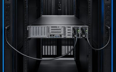
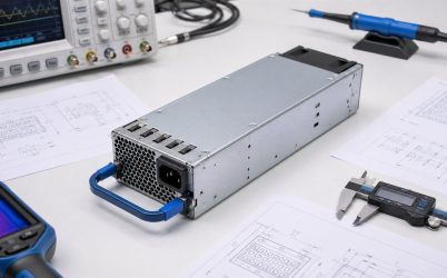
A CRPS power supply specification is a system interface definition, not a promise that every module with a similar shape is interchangeable. A complete review covers the mechanical envelope, blind-mate connector, input and output limits, standby rail, control and status signals, current sharing, hot-swap behavior, PMBus management, airflow, thermal derating, protection, safety, and host firmware expectations. The exact module revision and the server’s PDB must agree in each area. Compatibility should therefore be established with controlled documents and a production-chassis validation rather than appearance, wattage, or the CRPS name alone.
Quick answer: turn the specification into an interface matrix
Create one matrix with a column for the candidate PSU, mating PDB, chassis, BMC firmware, and facility input. List physical dimensions and keying; every power, return, sense, control, and communication contact; voltage and current limits; sequencing and timing; airflow; derating; protection; telemetry; and redundancy behavior. Mark each item as documented, measured, or unresolved. Use exact drawings and pin definitions for the offered model. Then test startup, dynamic load, thermal operation, module loss, live insertion, and management reporting. A module should be released only when all required interfaces agree and unresolved differences have been closed.
Identify the governing document and exact revision
CRPS can be used broadly for common redundant power-supply form factors, while specific ecosystems publish their own requirements and revisions. The first engineering task is to identify which document the host and module claim to follow. Record the issue date or revision, any implementation notes, and the exact product revision. A module designed around one version may not implement every optional or later function expected by another platform.
Separate normative requirements from vendor-specific additions. Mechanical and connector conventions may be shared, while telemetry commands, firmware identification, power levels, cooling behavior, and fault policy remain product-specific. If the host vendor provides an approved-parts list, treat it as important evidence. If an alternative module is proposed, the supplier should provide a cross-reference backed by testing rather than a statement that the unit is “CRPS compatible.”
Mechanical fit includes more than width and height
Compare height, width, depth, insertion envelope, guide-rail features, connector datum, keying, latch position, handle travel, and extraction clearance. The PSU must seat fully without excessive force and maintain reliable connector engagement through tolerance, vibration, and thermal expansion. A small depth or datum difference can leave contacts partially engaged even when the rear panel appears aligned.
Service clearances matter in a populated rack. Confirm that a technician can operate the latch and remove the module without disconnecting neighboring network or power cables. Check cord retention, LED visibility, labeling, finger access, and prevention of insertion into an incompatible bay. Any exact dimension must come from the current mechanical drawing for the exact model.
Input requirements define available output
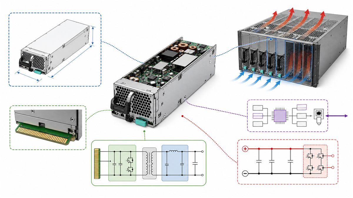
Document input voltage and frequency range, maximum current, inrush, power factor, leakage, ride-through behavior, connector, cord, and branch-circuit requirements. Many high-power server modules have output ratings that depend on input voltage. A unit advertised at one maximum wattage may provide less at low line. Redundancy capacity must be calculated from the rating available at the deployed input and temperature.
Consider facility events such as short interruptions, UPS transfer, generator operation, and phase or branch maintenance. The PSU’s hold-up behavior and the server’s allowable bus dip must coordinate. Input redundancy also needs independent paths if the design intends to tolerate a PDU or branch failure. Plugging both modules into one PDU protects against some PSU failures but preserves that upstream single point.
Map the main output and standby rail separately
The main rail supplies the server’s high-power loads through the PDB. The standby rail may power BMC, monitoring, and startup logic while the main output is disabled. Record nominal values, regulation limits, continuous and peak current, ripple, capacitive-load allowance, remote-sense behavior, startup timing, discharge, and backfeed restrictions for each rail. Do not generalize a rail voltage or current from another CRPS model.
High-current paths require a connection budget. Connector contacts, PDB copper, busbars, cables, fuses, ORing devices, and downstream converters each contribute resistance and temperature rise. Verify the voltage delivered at the point of load under normal sharing and after one module is removed. Sense contacts should be routed according to the specification, with defined behavior if a sense lead is open or shorted.
Never infer the pinout from the enclosure
A blind-mate connector can include main power, returns, protective or chassis contacts, standby power, enable, power-good, present, fault, current-share, remote-sense, address, and management-bus signals. Contact lengths may create a required mating sequence. The exact assignment and sequence must come from the module and host documents. A physical mating test without an electrical cross-check can damage equipment.
Build a pin-by-pin comparison that includes direction, voltage domain, pull-ups, logic level, maximum current, default state, timing, and behavior when disconnected. Review return-path allocation rather than counting only positive contacts. If multiple contacts share current, use the specified derating and verify engagement across tolerance. Signal names that look similar can still have different polarity or timing.
Control timing determines whether startup is clean
Enable and power-good signals coordinate the PSU with the server. Relevant parameters can include assertion and deassertion thresholds, delays, rise time, fall time, standby availability, and response to input loss. The PDB and BMC must interpret these signals correctly. A module that produces the correct voltage may still cause boot loops if timing falls outside the host’s expectation.
Load sequencing downstream also matters. Processor, memory, storage, and accelerator converters can create staged transients. The CRPS module and bulk capacitance must maintain the bus while point-of-load stages start. Test both cold input application and warm enable transitions at input and temperature extremes.
Current sharing and ORing create redundant behavior
Active current sharing aims to distribute load between modules, but it is not normally perfect. Define allowed imbalance and verify it across load, input, and temperature. Unequal sharing can push one module toward a thermal or current limit while total system power still appears acceptable. Telemetry from each PSU helps reveal this condition.
Output isolation prevents a faulted or unpowered module from collapsing the common bus. It may be implemented inside the PSU, on the PDB, or as a coordinated combination. Review reverse-current behavior, short-circuit isolation, failover, and recovery. In a 1+1 system, either module must carry the permitted server load after the other fails, including credible workload transients and the thermal impact of changed airflow.
Hot swap is a sequenced electrical event
Hot swap requires more than a removable handle. During extraction, contacts disengage in a controlled order and the healthy module maintains the bus. During insertion, protective and return contacts, precharge or presence functions, and main power must engage as designed. Inrush limiting prevents discharged input or output capacitance from producing excessive connector stress or bus disturbance.
The service procedure should identify the failed bay, confirm redundancy and load margin, specify safe removal, and define checks after insertion. Qualification should capture the shared DC bus with an oscilloscope during removal and reinsertion at representative loads. Verify alarms, event logs, new-module identification, current-share recovery, and fan behavior.
PMBus support is not identical across modules
PMBus may expose input voltage, input power, output current, temperature, fan speed, warnings, faults, manufacturer information, and control functions. Exact command coverage, data format, scaling, accuracy, update rate, addressing, and page behavior vary. The BMC may require particular identity fields or firmware behavior before accepting a supply as supported.
Create a command matrix and exercise normal, warning, and fault states. Compare telemetry with external calibrated instruments if the data will drive capacity management or automated response. Test bus recovery from a missing or unresponsive module. Also verify that replacing a PSU does not create an address conflict or leave stale fault information in the host.
Airflow direction and derating limit usable capacity
Server cooling paths are directional. A reverse-airflow module can oppose chassis fans or recirculate hot exhaust. Confirm airflow direction, maximum impedance, fan control, acoustic expectations, and behavior after one module is removed. Blank panels or bay geometry may be needed to prevent bypass and recirculation when a slot is empty.
Review output derating against inlet temperature, altitude, input voltage, and airflow. Use the worst combination that can occur in the rack. Measure inlet and exhaust temperatures and inspect connector, ORing, and PDB hot spots at sustained load. The maximum label rating is not necessarily the capacity available under every supported condition.
Protection must isolate the failing path
Review overvoltage, overcurrent, short-circuit, overtemperature, fan-fault, and input-fault responses. Note threshold ranges, delays, latching or automatic recovery, and interaction with the host. In a redundant design, a single internal fault should not propagate through the shared output within the defined fault model. External branch protection and PDB protection must coordinate with the module.
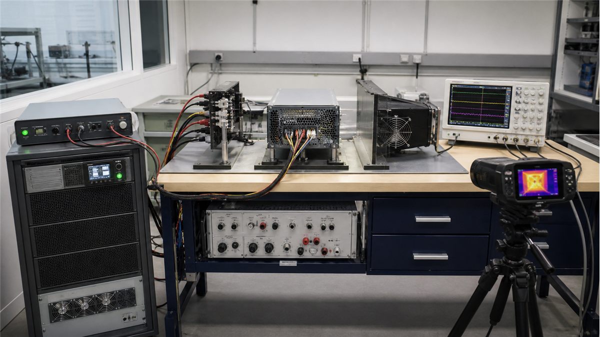
Fault testing should be controlled and based on safe procedures. Verify what the BMC reports, whether the correct service indicator activates, and whether the healthy module remains within limits. Recovery matters as much as trip behavior: repeated restart attempts, latched shutdown, or a silent return to operation can have different operational consequences.
A production qualification matrix
- Mechanical fit, full seating, latch, keying, extraction, and connector tolerance
- Minimum, nominal, and maximum input with rated and derated output
- Standby and main-rail startup, shutdown, timing, ripple, and load steps
- Pinout, sense, control, current-share, and power-good behavior
- PMBus identity, commands, telemetry, alarms, and BMC acceptance
- Normal sharing, single-module capacity, feed loss, removal, and reinsertion
- High-temperature, altitude, airflow, fan-fault, and empty-bay conditions
- Protection, fault isolation, recovery, event logging, safety, and EMC evidence
Retain the results with the module part number, hardware revision, firmware revision, PDB revision, BMC version, chassis configuration, and test conditions. This record prevents a later purchasing substitution from being treated as equivalent without evidence.
Powernexu’s standard CRPS compatibility guide complements this specification checklist, while the CRPS PDB design article focuses on the shared distribution interface. For current open-hardware documents, consult the Open Compute Project’s official DC-MHS specifications and designs and verify the revision relevant to the project.
Frequently resolved specification questions
Does CRPS define one universal connector pinout?
No universal assumption should be made. Use the exact governing specification, module documentation, and host PDB definition. Options, revisions, and vendor-specific functions can change assignments and behavior.
Can a higher-wattage CRPS module replace a lower-wattage unit?
Only if the host explicitly supports the exact module or qualification proves every required interface. Higher capacity does not guarantee the same depth, connector, rail, signals, firmware, cooling, or current-share behavior.
Is PMBus required for the PSU to provide output?
That depends on the module and host design. Some units can produce power with limited management communication, while a server BMC may reject or restrict an unidentified module. Verify the documented startup and host policy.
What is the most important redundancy test?
There is no single sufficient test. At minimum, verify that each individual module can support the permitted load under worst supported input and thermal conditions, and that removal, feed loss, fault isolation, alarm reporting, and reinsertion do not disrupt the shared bus beyond system limits.