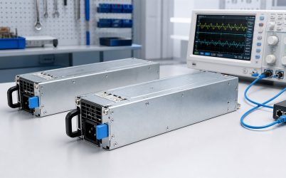
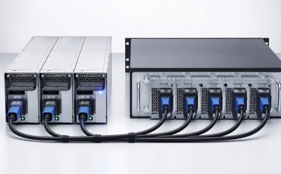
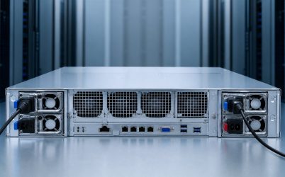
A rackmount redundant power supply must preserve power while fitting into a constrained rear-panel and service envelope. The design problem is spatial as much as electrical: two or more modules need guide rails, blind-mate connectors, extraction handles, independent cords, exhaust area, and a distribution board, while the same rear panel may also carry expansion cards and network ports. A valid rackmount design answers three questions together: can a surviving module carry the load, can the failed module be isolated, and can a technician replace it without disturbing the remaining power path or adjacent cabling?
Lay out the service envelope before selecting modules
Start with the rack chassis at full depth and draw the PSU insertion and extraction path. Include handle rotation, latch motion, cable bend radius, cord-retention hardware, rear door, cable-management arm, neighboring patch cords, and rack PDU position. A module that fits within the sheet-metal opening may still be impossible to remove after the server is cabled.
Inside the chassis, account for PSU depth, connector datum, guide tolerance, PDB, fan wall, motherboard, accelerator zone, and structural cross-members. The blind-mate connector should not be used to correct rail misalignment. Chassis guides and connector float must accommodate manufacturing tolerance without partial contact engagement.
1U, 2U, and larger chassis create different compromises
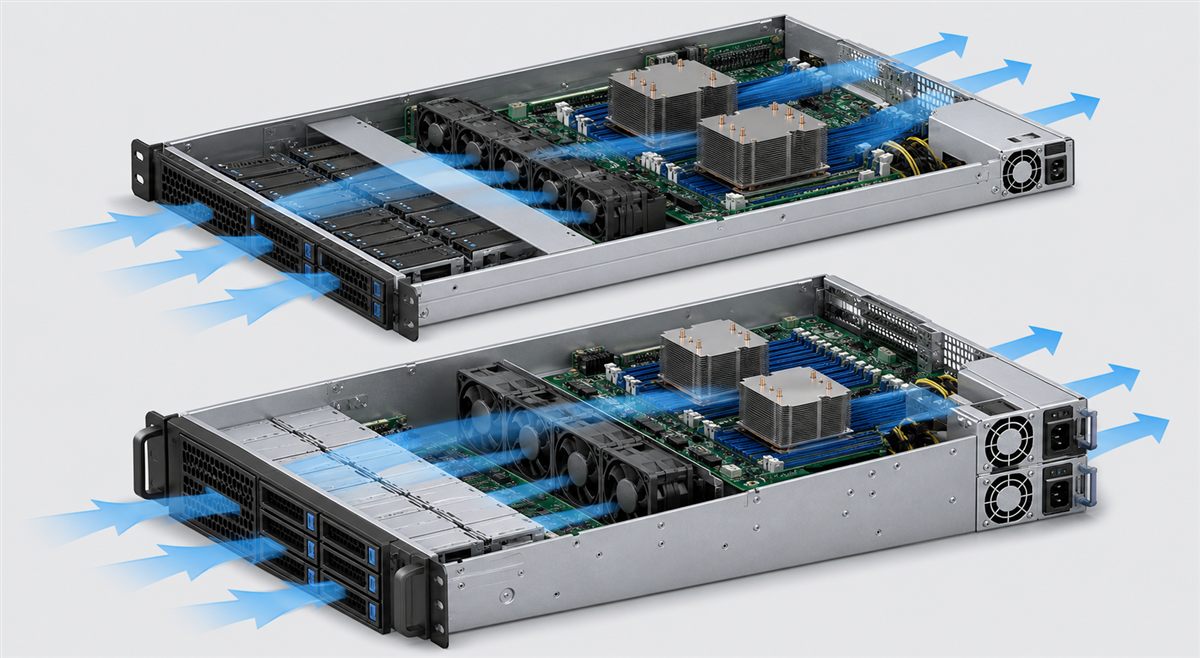
A 1U server has very limited module height and narrow air passages. Small fans may run at high speed, and vertically stacked connectors are difficult. A 2U system can arrange modules horizontally or vertically while balancing PCIe expansion, storage, and fan placement. Larger chassis may use more than two modules for N+1 capacity, but higher total current increases PDB and busbar demands.
These are layout tendencies rather than universal dimensions. The exact module drawing and chassis model control the decision. Preserve exhaust area and avoid placing cable bundles directly against PSU fans. If modules use reverse airflow variants, key or label the bay so the wrong direction cannot be installed.
Rear-panel allocation determines the redundancy topology
Two PSU bays commonly support 1+1 operation, where either module carries the permitted load. Three or more bays can support N+1 arrangements when N healthy modules meet demand. The rear panel must reserve sufficient inlet, handle, indicator, and ventilation area for every module. Adding another bay may reduce expansion slots or require a deeper internal distribution assembly.
Do not add module ratings to state redundant capacity. The server load must remain within the capacity available after the defined module loss. At low input voltage, high inlet temperature, altitude, or restricted airflow, usable output may be lower than the nameplate value.
Independent cords need a maintainable path to A and B PDUs
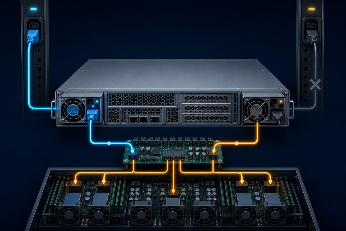
Feed each redundant module from an appropriately independent source when the availability requirement includes PDU or branch loss. Route cords so the A cable does not obstruct access to PSU B and vice versa. Consistent colors and labels at both ends reduce the chance that later rack work moves both modules to one PDU.
Cord length and bend radius affect service. Excess cable stuffed behind the chassis can block exhaust; a tight cable can pull on the inlet as the server slides. Use rack cable-management hardware that preserves the extraction path and keeps the rear door from pressing against plugs.
The PDB joins mechanics to high-current distribution
The PDB aligns with each blind-mate connector and combines outputs through an isolation architecture. It may route standby, enable, power-good, presence, fault, current-share, remote-sense, address, and PMBus signals. Exact pin assignments are model-specific; shared module shape does not prove compatibility.
After one module is removed, the surviving connector and PDB path carry more current. Copper transitions, ORing devices, shunts, vias, and downstream connectors must remain within voltage-drop and temperature limits. A higher-wattage replacement cannot increase a PDB rating established by its own construction.
Airflow changes during a live service event
Removing a module opens a low-resistance path through the rear panel. Chassis air can bypass processors or recirculate through the empty bay. The surviving PSU also generates more heat as it takes the full load. Some systems depend on an immediate replacement; others specify a blanking device for an extended empty-bay condition.
Thermal testing should compare normal sharing, one module disabled, one module physically removed, and the replacement inserted. Measure PSU inlet and exhaust, connector, ORing stage, PDB, and nearby components. Use production fan policy, rack doors, cable arrangement, and representative neighboring equipment.
Rack depth and sliding rails create hidden interferences
Chassis depth is usually specified without every rear attachment in its deployed position. Add the PSU handle, plug body, cord bend, retention clip, cable arm, and rear-door clearance to the spatial model. A shallow cabinet or densely mounted vertical PDU can leave too little room for the module latch or force the cord into the exhaust stream. If the server slides forward for service, both power cords must travel without pulling against their inlets.
Test the complete rail motion while the server is powered from both paths. Observe whether the cable arm twists A and B cords together, presses them against hot exhaust, or transfers force to neighboring connectors. Service loops should be long enough for movement but controlled so they cannot fall into fans or obstruct an adjacent PSU. These mechanical details often decide whether redundant power remains available during unrelated motherboard or storage maintenance.
Hot swap is a rack service capability, not a handle feature
A live-removable module needs sequenced contacts, output isolation, inrush control, mechanical guidance, and host control logic. Before removal, the operator identifies the failed bay and confirms the healthy path and load margin. Pulling the healthy module can shut down the server.
During insertion, the incoming module should engage in the intended order, initialize standby and management functions, enable the main output, and join current sharing without pulling the bus outside limits. BMC alarms should clear only after redundancy is genuinely restored.
Use a rack-level failure walk-through
| Event | Physical observation | Electrical requirement |
|---|---|---|
| PSU A loses input | A cord or PDU path is inactive | PSU B and its path carry full load |
| PSU A is extracted | Open bay changes airflow | Isolation prevents bus disturbance |
| Replacement enters bay | Guides and latch align connector | Inrush and sequencing remain controlled |
| Rear door closes | Cords and handles retain clearance | Exhaust remains unobstructed |
| Server slides for service | Cable arm moves without tension | Both inputs remain securely connected |
Commission the server in its actual rack position
- Inspect module and PDB drawings, guide alignment, latch engagement, and connector seating.
- Install the server on production rails with its cable-management arm and rear door.
- Connect PSU A and B to their intended rack power paths and audit separation.
- Exercise startup, idle, representative workload, and maximum redundant load.
- Run on each module alone and monitor the main bus, current, alarms, and temperatures.
- Remove and insert each approved module using the documented procedure.
- Inspect cord access and exhaust after neighboring cables and equipment are installed.
- Record the validated configuration, load limit, spare part, and service steps.
When a rackmount redundant design is justified
The architecture is appropriate when the cost of an outage exceeds the additional module, PDB, rack feed, space, and maintenance cost. A development or noncritical server may use one fixed supply and a planned replacement. An enterprise, storage, network, or industrial server with continuity requirements may justify 1+1 hot-swap modules and A/B inputs.
The choice should follow the protected failure set. Two modules on one PDU provide narrower protection than two modules on independent rack paths. A multi-module N+1 design provides capacity reserve but may not survive loss of an entire feed group unless module placement supports it.
Compatibility boundaries for replacement modules
Replacement requires matching the host’s mechanical, electrical, thermal, and management interface. Compare depth, connector, keying, pinout, output and standby rails, current share, control timing, PMBus identity, airflow, input range, and firmware support. A module can fit the bay yet be rejected by the BMC or share current incorrectly.
Powernexu’s rackmount server power supply integration article covers nonredundant and redundant chassis selection more broadly. The rack server redundant power failure-path guide expands on A/B feed behavior.
Spare strategy belongs to the mechanical architecture
A redundant chassis provides continuity only until another path is lost, so replacement logistics matter. Stock the exact approved module or a documented compatible revision, and store it where the response team can access it within the required repair window. A generic spare chosen by wattage can introduce a different latch, connector datum, airflow direction, or firmware identity at the worst possible time.
Include the spare in periodic service drills. Confirm that its packaging protects connector contacts, that its revision remains supported by the current BMC, and that the rack procedure identifies which cord and bay must remain untouched. If a product revision changes, update the spare pool and qualification record together.
The rack acceptance decision
A rackmount redundant power supply design is complete when a technician can identify and replace one failed module, the other module and feed can sustain the approved workload, fault current is isolated, airflow remains acceptable, and cords stay separated and accessible in the real cabinet. The final evidence is not an extra PSU on the bill of materials; it is a rack-level test showing continuity through the intended failure and service sequence.